• 4.9/5.0
  • 246 Questions
  • Updated on: 12-Oct-2026
  • Implementing Cisco Application Centric Infrastructure (300-620 DCACI)
  • 22465 Prepared

Free Cisco 300-620 Practice Questions 2026 | Implementing Cisco Application Centric Infrastructure (300-620 DCACI)
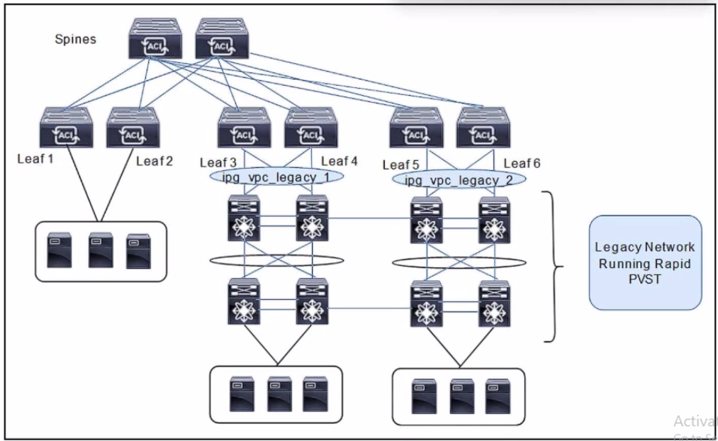


Refer to the exhibit. A client is configuring a new Cisco ACI fabric. All VLANs will be extended during the migration phase using the VPC connections on leaf switches 3. 4 and leaf switches toward the legacy network. The migration phase has these requirements;

* If The legacy switches must be able to transfer BPDUs through the ACI fabric.

* If the legacy switches fail to break a loop. Cisco ACI must break the loop.

Which group settings must be configured on VPC interface policy groups ipg_vpc-legacy_1 and ipg_vpc-legacy_2 to meet these requirements?

A. MCP: enabled
BPDU Guard: enabled
BPDU Filter: disabled

B. MCP: enabled
BPDU Guard: disabled
BPDU Filter: disabled

C. MCP: disabled
BPDU Guard: disabled
BPDU Filter: enabled

D. MCP: disabled
BPDU Guard: enabled
BPDU Filter enable

B.   MCP: enabled
BPDU Guard: disabled
BPDU Filter: disabled

Explanation:
During the migration phase, the legacy network runs Rapid PVST and connects to the ACI fabric through vPC connections on Leaf 3/4 and Leaf 5/6. The requirements are:

Legacy switches must be able to transfer BPDUs through the ACI fabric.

If the legacy switches fail to break a loop, ACI must break the loop.

To meet these requirements, the vPC interface policy groups must be configured as follows:

Correct Option:

MCP: enabled:
MCP (Mis-Cabling Protocol) is ACI's loop-prevention protocol. Enabling MCP allows the ACI fabric to detect and break loops if the legacy switches fail to do so. MCP sends PDUs on the vPC interfaces and can disable ports if a loop is detected.

BPDU Guard: disabled: BPDU Guard should be disabled because the legacy switches need to send BPDUs through the ACI fabric. If BPDU Guard were enabled, it would shut down the port upon receiving BPDUs, breaking the spanning tree topology and preventing the legacy switches from participating in STP.

BPDU Filter: disabled: BPDU Filter should be disabled because the BPDUs must be allowed to pass through the ACI fabric. If BPDU Filter were enabled, it would block BPDUs from being forwarded, which would prevent the legacy switches from exchanging STP information and maintaining a loop-free topology.

Incorrect Option:

A. BPDU Guard: enabled:
Enabling BPDU Guard would shut down the vPC ports when BPDUs are received from the legacy switches. This would prevent the legacy switches from transferring BPDUs and break the required STP connectivity.

C. MCP: disabled, BPDU Filter: enabled:
Disabling MCP removes ACI's ability to break loops if the legacy switches fail. Enabling BPDU Filter would block BPDUs, which violates the requirement that legacy switches must be able to transfer BPDUs.

D. MCP: disabled, BPDU Guard: enabled, BPDU Filter: enabled:
This combination is the opposite of what is required. MCP is disabled (no loop protection from ACI), BPDU Guard is enabled (would shut down ports on BPDU receipt), and BPDU Filter is enabled (would block BPDUs). This would completely break the migration requirements.

Reference:
Cisco ACI Layer 2 Networking Configuration Guide — "MCP and BPDU Handling on vPC Interfaces": For migrations where legacy switches must exchange BPDUs through the ACI fabric, BPDU Guard and BPDU Filter must be disabled. MCP should be enabled to provide loop protection if the external spanning tree fails to break a loop.
An ACI engineer is implementing a Layer 3 out inside the Cisco ACI fabric that must meet these requirements:

The data center core switch must be connected to one of the leaf switches with a single 1G link.

The routes must be exchanged using a link-state routing protocol that supports hierarchical network design.

The data center core switch interface must be using 802.1Q tagging, and each vlan will be configured with a dedicated IP address.

Which set of steps accomplishes these goals?

A. Set up the ElGRP Protocol policy with the selected Autonomous System number. Set up the Routed External Network object ana Node Profile, selecting ElGRP Create the Switch profile, selecting Port-channel and the appropriate interfaces Create the default network and associate it with the Routed Outside object.

B. Set up the BGP Protocol policy with the Autonomous System number of 0.
Configure an interface policy and an External Bridged Domain.
Create an External Bridged Network using the configured VLAN pool.
Build the Leaf profile, selecting Routed sub-interface and the appropriate VLAN.

C. Configure the OSPF Protocol policy with an area of 0.
Create Routed Outside object and Node Profile, selecting OSPF as the routing protocol.
Build the Interface profile, selecting Routed Sub-interface and the appropriate VLAN.
Configure the External Network object with a network of 0.0.0.0/0.

D. Set up the ElGRP Protocol policy with the selected Autonomous System number. Create the Routed Outside object and Node Profile selecting ElGRP Configure the Interface profile selecting Routed Interface and the appropriate interfaces. Create the External Network object with a network of 0.0.0.0/0.

C.   Configure the OSPF Protocol policy with an area of 0.
Create Routed Outside object and Node Profile, selecting OSPF as the routing protocol.
Build the Interface profile, selecting Routed Sub-interface and the appropriate VLAN.
Configure the External Network object with a network of 0.0.0.0/0.

Explanation

Let's break down the requirements and match them to the correct configuration steps:

"The data center core switch must be connected to one of the leaf switches with a single 1G link."

This indicates a physical connection to a single leaf switch. No port-channel or vPC is required, as it's a single link. This rules out options that mention port-channels (Option A).

"The routes must be exchanged using a link-state routing protocol that supports hierarchical network design."

The key phrase here is link-state routing protocol. The two main link-state protocols are OSPF (Open Shortest Path First) and IS-IS (Intermediate System to Intermediate System). In the context of ACI L3Out, OSPF is the supported link-state protocol. EIGRP is an advanced distance-vector protocol, and BGP is a path-vector protocol. This eliminates options that use EIGRP (Options A and D) or BGP (Option B).

OSPF supports hierarchical network design through the use of areas (e.g., Area 0, the backbone area). This is a core feature of OSPF, satisfying the "hierarchical" requirement.

"The data center core switch interface must be using 802.1Q tagging, and each vlan will be configured with a dedicated IP address."

This explicitly describes a sub-interface configuration. A physical interface (Routed Interface) can only have one IP address and is not associated with 802.1Q tagging. A Routed Sub-interface is a logical interface that uses a VLAN ID for 802.1Q tagging and can have its own dedicated IP address. This means the interface type must be a Routed Sub-interface, which eliminates options that use a Routed Interface (Option D).

Correct Option

C. Configure the OSPF Protocol policy with an area of 0.

This step correctly identifies the routing protocol (OSPF) and its hierarchical component (Area 0).

Create Routed Outside object and Node Profile, selecting OSPF as the routing protocol.

This is the standard ACI workflow for creating an L3Out. The "Routed Outside" is the logical construct for the L3Out, and the Node Profile defines which leaf switches participate.

Build the Interface profile, selecting Routed Sub-interface and the appropriate VLAN.

This step correctly addresses the requirement for 802.1Q tagging and dedicated IP addresses per VLAN by selecting a Routed Sub-interface and specifying the VLAN.

Configure the External Network object with a network of 0.0.0.0/0.

This is a standard practice for an L3Out that acts as a default route to the external network. The External Network object (External EPG) with 0.0.0.0/0 allows all external destinations to be reachable via this L3Out.

Incorrect Option

A. Uses EIGRP and Port-channel:
Incorrect. The requirement specifies a link-state protocol (OSPF), and the connection is a single 1G link, not a port-channel.

B. Uses BGP and an External Bridged Domain:
Incorrect. The requirement specifies a link-state protocol (OSPF), and an External Bridged Domain is for L2Out, not L3Out.

D. Uses EIGRP and Routed Interface:
Incorrect. The requirement specifies a link-state protocol (OSPF), and a Routed Interface does not support 802.1Q tagging with multiple VLANs.

Reference
Cisco APIC Layer 3 Networking Configuration Guide — "Configuring an L3Out with OSPF": OSPF is a supported link-state routing protocol for L3Out. Routed sub-interfaces are used for 802.1Q tagging. The External Network object is configured with a network to define the external subnets reachable through the L3Out.

Cisco ACI fabric must detect all silent endpoints for the Layer 3 bridge domain. Which actions accomplish this goal?

A. Disable Unicast Routing.

Enable L2 Unknown Unicast Hardware Proxy.

B. Disable Unicast Routing.

Enable L2 Unknown Unicast Flood.

C. Enable Unicast Routing. Disable ARP Flooding.

D. Enable Unicast Routing. Enable ARP Flooding.

C.   Enable Unicast Routing. Disable ARP Flooding.

Explanation:
To detect silent endpoints (hosts that do not send traffic or ARP requests) in a Layer 3 bridge domain, the fabric must be able to resolve IP-to-MAC bindings without relying on the endpoint to generate traffic. Enabling Unicast Routing makes the bridge domain act as the default gateway and enables IP-based endpoint learning. Disabling ARP Flooding forces the fabric to perform ARP gleaning, where the leaf switch intercepts ARP requests and responses to learn the endpoint's IP and MAC addresses.

Correct Option:

C. Enable Unicast Routing. Disable ARP Flooding:
This is correct. With Unicast Routing enabled, the bridge domain performs IP-based endpoint learning. Disabling ARP Flooding enables ARP gleaning, which allows the fabric to learn silent endpoints by intercepting ARP traffic. This combination ensures that silent endpoints are detected and learned even if they do not actively send data-plane traffic.

Incorrect Option:

A. Disable Unicast Routing. Enable L2 Unknown Unicast Hardware Proxy:
Disabling Unicast Routing prevents IP-based endpoint learning, which is required for Layer 3 bridge domains. Hardware Proxy is a Layer 2 forwarding setting and does not help detect silent endpoints.

B. Disable Unicast Routing. Enable L2 Unknown Unicast Flood:
Disabling Unicast Routing again prevents IP learning. Flooding unknown unicast may help reach endpoints but does not detect or learn silent endpoints in the endpoint table.

D. Enable Unicast Routing. Enable ARP Flooding:
Enabling Unicast Routing is correct, but enabling ARP Flooding allows ARP requests to be flooded across the bridge domain, which can cause the fabric to learn ARP entries from flooded traffic. However, the question specifically asks for the actions to detect silent endpoints. Disabling ARP Flooding is the recommended configuration for silent endpoint detection because it forces ARP gleaning, which is more efficient for learning silent endpoints.

Reference:
Cisco ACI Fundamentals — "Silent Endpoint Detection": To detect silent endpoints in a Layer 3 bridge domain, enable Unicast Routing and disable ARP Flooding. This configuration enables ARP gleaning, allowing the fabric to learn IP-to-MAC bindings for silent endpoints.


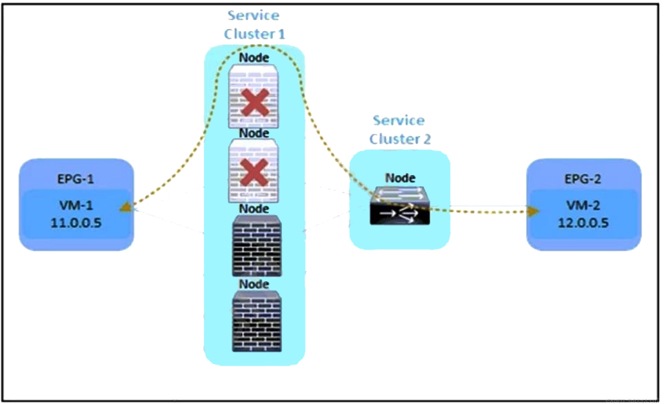
Refer to the exhibit. An engineer must divert the traffic between VM-1 and VM-2 by using a Multi-Node service graph. The solution should prevent an insufficient number of available Layer 4 to Layer 7 devices in the first cluster. Which configuration set accomplishes this goal?

A. PBR node tracking
tracking threshold with action bypass
symmetric PBR
resilient hashing

B. PBR node tracking
tracking threshold with action permit
unidirectional PBR
resilient hashing

C. PBR node tracking
tracking threshold with action permit
symmetric PBR
resilient hashing

D. PBR node tracking
tracking threshold with action deny
symmetric PBR
unidirectional PBR

A.   PBR node tracking
tracking threshold with action bypass
symmetric PBR
resilient hashing

Explanation:
The exhibit shows a Multi-Node service graph with two service clusters. The requirement is to divert traffic between VM-1 and VM-2 while preventing an insufficient number of available L4-L7 devices in the first cluster. To achieve this, the engineer needs to enable Policy-Based Redirect (PBR) node tracking to monitor the health of service nodes. When the number of available nodes falls below a configured threshold, the action should be bypass, which allows traffic to skip the service cluster and continue to its destination. Additionally, symmetric PBR ensures that return traffic follows the same path, and resilient hashing ensures that traffic is distributed across the available nodes while minimizing disruption when nodes are added or removed.

Correct Option:

PBR node tracking:
This feature monitors the health of service nodes and tracks the number of available nodes in a service cluster. It is essential for detecting when the cluster has insufficient available devices.

tracking threshold with action bypass: When the number of available nodes drops below the configured threshold, the action bypass allows traffic to bypass the service cluster entirely, preventing traffic from being dropped due to insufficient service nodes.

symmetric PBR: This ensures that traffic in both directions (VM-1 to VM-2 and VM-2 to VM-1) is redirected through the same service nodes, maintaining stateful inspection and consistent policy enforcement.

resilient hashing: This feature ensures that traffic flows are redistributed across the remaining available nodes when a node fails or is removed, minimizing disruption and maintaining even load distribution.

Incorrect Option:

B. tracking threshold with action permit:
The action permit would allow traffic to be sent to the service cluster even when the threshold is not met, which could result in traffic being dropped if there are insufficient available nodes. The requirement is to prevent insufficient nodes, so bypass is the correct action.

C. tracking threshold with action permit:
Same as option B, the action permit is incorrect for this scenario.

D. tracking threshold with action deny:
The action deny would drop traffic when the threshold is not met, which is not the desired behavior. The requirement is to divert traffic, not to drop it. Bypass allows traffic to continue without service insertion, which is the correct action.

Reference:
Cisco APIC Layer 4 to Layer 7 Services Deployment Guide — "PBR Node Tracking": PBR node tracking monitors the health of service nodes and triggers an action (bypass or permit) when the number of available nodes falls below a threshold. Symmetric PBR ensures return traffic follows the same path. Resilient hashing provides even distribution and minimal disruption during node changes.

An engineer must allow multiple external networks to communicate with internal ACI subnets. Which action should the engineer take to assign the prefix to the class ID of the external Endpoint Group?

A. Enable the Export Route Control Subnet for the External Endpoint Group flag.

B. Enable an L30ut with Shared Route Control Subnet.

C. Configure subnets with the External Subnets for External EPG flag enabled.

D. Configure subnets with the Import Route Control Subnet flag enabled.

C.   Configure subnets with the External Subnets for External EPG flag enabled.

Explanation:
In Cisco ACI, the External Subnets for External EPG flag is used to assign a prefix to the class ID of an external Endpoint Group. This flag allows the external EPG to classify traffic based on the specified subnet. When this flag is enabled on a subnet within an L3Out's external EPG, the fabric uses that subnet to match incoming traffic and associate it with the external EPG, enabling communication with internal ACI subnets.

Correct Option:

C. Configure subnets with the External Subnets for External EPG flag enabled:
This is the correct action. The External Subnets for External EPG flag (also known as the External Subnets for the External EPG option) is used to assign a prefix to the class ID of an external EPG. This allows the external EPG to match traffic from the specified subnet and apply the appropriate contracts and policies.

Incorrect Option:

A. Enable the Export Route Control Subnet for the External Endpoint Group flag:
The Export Route Control Subnet flag is used to control which subnets are advertised externally through the L3Out. It does not assign a prefix to the class ID of an external EPG.

B. Enable an L30ut with Shared Route Control Subnet:
The Shared Route Control Subnet flag is used to share subnets between VRFs. It does not assign a prefix to the class ID of an external EPG.

D. Configure subnets with the Import Route Control Subnet flag enabled:
The Import Route Control Subnet flag is used to control which external routes are imported into the ACI fabric. It does not assign a prefix to the class ID of an external EPG.

Reference:
Cisco APIC Layer 3 Networking Configuration Guide — "External Subnets for External EPG": The External Subnets for External EPG flag is used to classify traffic from external networks into an external EPG based on the subnet. This allows contracts to be applied to traffic from those subnets.

The company’s Cisco ACI fabric hosts multiple customer tenants. To meet a service level agreement, the company is constantly monitoring the Cisco ACI environment. Syslog is one of the methods used for monitoring. Only events related to leaf and spine environmental information without specific customer data should be logged. To which ACI object must the configuration be applied to meet these requirements?

A. access policy

B. infra tenant

C. switch profile

D. fabric policy

D.   fabric policy

Explanation:
To monitor leaf and spine environmental information (such as temperature, power supply status, fan status, and other hardware-related events) without capturing customer-specific data, the syslog configuration must be applied at the fabric policy level. This ensures that the monitoring scope is limited to the fabric infrastructure itself, not to tenant-specific objects or EPG-level traffic.

Correct Option:

D. fabric policy:
The fabric policy is the correct object for configuring syslog monitoring for leaf and spine environmental information. Syslog policies configured at the fabric level apply to the fabric nodes (spines and leaves) and capture infrastructure-related events. This scope excludes tenant-specific data, satisfying the requirement to avoid logging customer-specific information.

Incorrect Option:

A. access policy:
Access policies are used to configure physical interface settings (such as LLDP, CDP, LACP, and VLAN pools). They do not control syslog monitoring scope.

B. infra tenant:
The infra tenant contains policies for fabric infrastructure, including in-band management and fabric discovery. While it is related to infrastructure, syslog monitoring for environmental events is configured under fabric policies, not the infra tenant.

C. switch profile:
Switch profiles are used to associate leaf or spine switches with configuration policies, including access policies and monitoring policies. While a switch profile may reference a syslog policy, the actual monitoring scope is defined in the fabric policy.

Reference:
Cisco APIC Monitoring Guide — "Syslog Monitoring": Syslog policies for fabric nodes (spines and leaves) are configured under Fabric > Fabric Policies > Monitoring Policies. This scope captures environmental and infrastructure events without including tenant-specific data.

Which switch type is discovered first in the Cisco ACI fabric discovery process?

A. leaf

B. access

C. distribution

D. spine

A.   leaf

Explanation:
In the Cisco ACI fabric discovery process, the leaf switches are discovered first. The APIC controllers are connected to the leaf switches (typically through the management network or directly), and the discovery process begins with the leaf switches. Once a leaf switch is discovered, the APIC then discovers the spine switches connected to that leaf, and the discovery process cascades through the fabric topology.

Correct Option:

A. leaf:
Leaf switches are the first to be discovered. The APIC establishes communication with the leaf switches, and after a leaf is discovered, the APIC discovers the spine switches connected to it. The discovery then continues to other leaf switches through the spines.

Incorrect Option:

B. access:
"Access" is not a switch type in the ACI fabric discovery process. Access switches are a concept in traditional network designs, not ACI.

C. distribution:
"Distribution" is also not a switch type in ACI. Distribution switches are part of traditional three-tier network designs, not the ACI spine-leaf architecture.

D. spine:
Spine switches are discovered after the leaf switches. The discovery process starts with the leaf, then moves to the spine, and then cascades to other leaf switches.

Reference:
Cisco APIC Getting Started Guide — "Fabric Discovery Process": The APIC discovers leaf switches first, starting with the leaf directly connected to the APIC. Once a leaf is discovered, the APIC discovers the spine switches connected to that leaf.

In-band is currently configured and used to manage the Cisco ACI fabric. The requirement is for leaf and spine switches to use out-of-band management for NTP protocol. Which action accomplishes this goal?

A. Select Out-of-Band as Management EPG in the default DateTimePolicy.

B. Create an Override Policy with NTP Out-of-Band for leaf and spine switches.

C. Change the interface used for APIC external connectivity to ooband.

D. Add a new filter to the utilized Out-of-Band-Contract to allow NTP protocol.

B.   Create an Override Policy with NTP Out-of-Band for leaf and spine switches.

Explanation:
In Cisco ACI, the NTP configuration is managed through a Date and Time Policy (DateTimePolicy). By default, this policy uses the in-band management EPG for NTP traffic when in-band management is configured. To force leaf and spine switches to use the out-of-band management EPG for NTP instead, you must create an Override Policy specifically for NTP that specifies Out-of-Band as the management EPG, and apply it to the leaf and spine switches.

Correct Option:

B. Create an Override Policy with NTP Out-of-Band for leaf and spine switches:
This is the correct action. The override policy allows you to specify a different management EPG (in this case, Out-of-Band) for a specific protocol (NTP) on specific switches (leaf and spine), overriding the global Date and Time Policy setting that currently uses in-band management.

Incorrect Option:

A. Select Out-of-Band as Management EPG in the default DateTimePolicy:
Changing the default Date and Time Policy would affect all switches and all protocols, not just NTP for leaf and spine switches. It would also change the management EPG for other time-related protocols, which may not be desired.

C. Change the interface used for APIC external connectivity to ooband:
The APIC's external connectivity interface is separate from the NTP management path for leaf and spine switches. Changing the APIC interface does not affect how leaf and spine switches reach NTP servers.

D. Add a new filter to the utilized Out-of-Band-Contract to allow NTP protocol:
While the out-of-band contract must allow NTP traffic, adding a filter alone does not force the switches to use the out-of-band EPG for NTP. The override policy is required to direct NTP traffic to the out-of-band management EPG.

Reference:
Cisco APIC Basic Configuration Guide — "NTP Override Policy": The NTP override policy allows you to specify the management EPG (In-Band or Out-of-Band) for NTP traffic on a per-switch or per-switch-group basis. This overrides the global Date and Time Policy setting.

A network engineer must allow secure access to the Cisco ACl out-of-band (OOB) management only from external subnets 10 0 0024 and 192.168 20 G'25. Which configuration set accomplishes this goal?
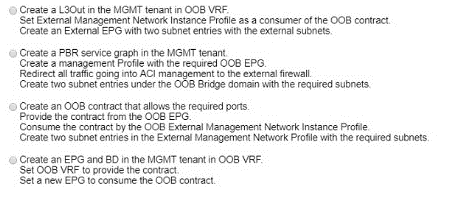
A. Option A

B. Option B

C. Option C

D. Option D

C.   Option C

Explanation:
The goal is to allow secure access to the Cisco ACI out-of-band (OOB) management interface only from specific external subnets (10.0.0.0/24 and 192.168.20.0/25). In ACI, this is achieved by creating an OOB contract that permits the required management protocols (HTTPS, SSH, etc.), providing that contract from the OOB EPG, and consuming it on the OOB External Management Network Instance Profile. The external subnets are then defined as subnet entries under the External Management Network Instance Profile, which restricts access to those specific subnets.

Correct Option:

C. Create an OOB contract that allows the required ports.
Provide the contract from the OOB EPG. Consume the contract by the OOB External Management Network Instance Profile. Create two subnet entries in the External Management Network Instance Profile with the required subnets: This is the correct configuration. The OOB contract defines the allowed management protocols. The OOB EPG provides the contract, and the External Management Network Instance Profile consumes it. The subnet entries in the External Management Network Instance Profile restrict access to the specified external subnets (10.0.0.0/24 and 192.168.20.0/25), ensuring that only traffic from those subnets is permitted.

Incorrect Option:

A. Create a L3Out in the MGMT tenant in OOB VRF.
Set External Management Network Instance Profile as a consumer of the OOB contract. Create an External EPG with two subnet entries with the external subnets: This option creates an L3Out and an External EPG, but it does not correctly define the contract consumption for the OOB management EPG. The External Management Network Instance Profile must consume the contract, not be a consumer of it in the way described.

B. Create a PBR service graph in the MGMT tenant.
Create a management Profile with the required OOB EPG. Redirect all traffic going into ACI management to the external firewall. Create two subnet entries under the OOB Bridge domain with the required subnets: This option involves PBR and an external firewall, which is not required for the stated goal. The requirement is to restrict OOB management access to specific subnets, not to redirect traffic through a firewall.

D. Create an EPG and BD in the MGMT tenant in OOB VRF.
Set OOB VRF to provide the contract. Set a new EPG to consume the OOB contract: This option creates an EPG and BD in the MGMT tenant, but it does not correctly configure the External Management Network Instance Profile with the required subnet entries to restrict access to the specified subnets.

Reference:
Cisco APIC Security Configuration Guide — "Out-of-Band Management Access": To restrict OOB management access to specific external subnets, create an OOB contract with the required filters, provide it from the OOB EPG, and consume it on the External Management Network Instance Profile. Configure the allowed subnets as entries in the External Management Network Instance Profile.

How is broadcast forwarded in Cisco ACI Multi-Pod after ARP flooding is enabled?

A. Ingress replication is used on the spines to forward broadcast frames in the IPN infrastructure.

B. Within a pod, the ingress leaf switch floods the broadcast frame on all fabric ports.

C. Broadcast frames are forwarded inside the pod and across the IPN using the multicast address that is associated to the bridge domain.

D. For the specific bridge domain, all spines forward the broadcast frames to IPN routers.

C.   Broadcast frames are forwarded inside the pod and across the IPN using the multicast address that is associated to the bridge domain.

Explanation:
In Cisco ACI Multi-Pod, when ARP flooding is enabled, broadcast frames are forwarded within the local pod using the fabric's internal flooding mechanism. Across the Inter-Pod Network (IPN), broadcast frames are replicated using PIM Bidirectional (PIM-Bidir) multicast. Each bridge domain is associated with a GIPO (Group IP Outer) multicast address, which is used to forward broadcast, unknown unicast, and multicast (BUM) traffic across the IPN to other pods.

Correct Option:

C. Broadcast frames are forwarded inside the pod and across the IPN using the multicast address that is associated to the bridge domain:
This is accurate. Within a pod, broadcast frames are flooded to all leaf switches that have the bridge domain deployed. For inter-pod communication, the spine switches forward the broadcast frames across the IPN using the multicast group address associated with the bridge domain. The IPN must support PIM-Bidir for this multicast replication.

Incorrect Option:

A. Ingress replication is used on the spines to forward broadcast frames in the IPN infrastructure:
Ingress replication is not used in Multi-Pod for BUM traffic. Multi-Pod uses PIM-Bidir multicast in the IPN for inter-pod BUM replication. Ingress replication is used in Multi-Site, not Multi-Pod.

B. Within a pod, the ingress leaf switch floods the broadcast frame on all fabric ports:
While the ingress leaf does flood the broadcast frame within the pod, it does not flood on "all fabric ports." It floods to all leaf switches that have the bridge domain deployed, using the fabric's VXLAN flooding mechanism. This option is partially correct but incomplete.

D. For the specific bridge domain, all spines forward the broadcast frames to IPN routers:
Not all spines forward broadcast frames to IPN routers. Only the spine switches that are connected to the IPN and participating in the multicast replication for that bridge domain forward the frames. The forwarding is based on the multicast group address, not simply "all spines."

Reference:
Cisco ACI Multi-Pod Design Guide — "BUM Traffic Forwarding": In Multi-Pod, BUM traffic is forwarded within a pod using the fabric's internal flooding. Across the IPN, PIM-Bidir multicast is used with the GIPO address associated with the bridge domain. The IPN must support PIM-Bidir for inter-pod BUM replication.

Page 9 out of 25 Pages