- 4.9/5.0
- 547 Questions
- Updated on: 12-Oct-2026
- Implementing and Operating Cisco Service Provider Network Core Technologies (350-501 SPCOR)
- 25475 Prepared
Free Cisco 350-501 Practice Questions 2026 | Implementing and Operating Cisco Service Provider Network Core Technologies (350-501 SPCOR)
Refer to the exhibit: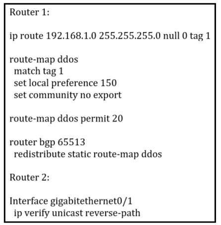
An engineer is preparing to implement data plane security configuration.
Which statement about this configuration is true?
A. Router 2 must configure a route to null 0 for network 192 168.1 0/24 for the RTBH implementation to be complete.
B. Router 1 is the trigger router in a RTBH implementation.
C. Router 1 must be configured with uRPF for the RTBH implementation to be effective.
D. Router 2 is the router receiving the DDoS attack
Explanation
In a Remote-Triggered Black Hole (RTBH) filtering setup, Router 1 serves as the trigger router where the administrative team injects the destination prefix under attack and sets a specialized next-hop (such as an unroutable IP).
Why Option A Is Incorrect
Edge routers (Router 2) do not point a static route for the actual victim network directly to Null 0. Instead, they point a static route targeting the dummy next-hop address (provided by the trigger router) to Null 0.
Why Option C Is Incorrect
Unicast Reverse Path Forwarding (uRPF) is deployed on ingress edge interfaces facing customer networks to drop IP spoofing packets, not on the core trigger router.
Why Option D Is Incorrect
The configuration exhibits how the routing infrastructure drops traffic destined for an attack prefix, but it does not specify which router is directly receiving the incoming volumetric DDoS traffic.
Reference
Cisco Official Documentation: Implementing and Operating Cisco Service Provider Network Core Technologies (SPCOR 350-501) — Chapter: Service Provider Security, Remote-Triggered Black Hole (RTBH) Filtering Architecture.
Refer to the exhibit.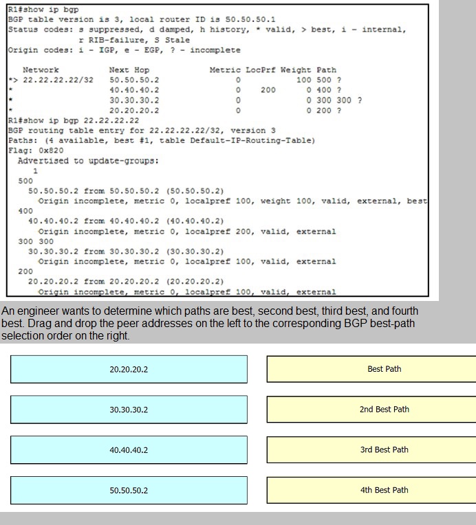

Explanation
1. Weight (Highest Wins)
Cisco’s first path-selection criterion is Weight, which is locally significant to the router. Path 50.50.50.2 is configured with a Weight of 100, while paths 40.40.40.2, 30.30.30.2, and 20.20.20.2 have the default Weight of 0.
Result: 50.50.50.2 wins immediately as the Best Path (1st).
2. Local Preference (Highest Wins)
For the remaining three paths with a Weight of 0, we check Local Preference. Path 40.40.40.2 has a Local Preference of 200, whereas 30.30.30.2 and 20.20.20.2 have a Local Preference of 100.
Result: 40.40.40.2 takes the 2nd Best Path.
3. AS Path Length (Shortest Wins)
Comparing the final two paths (30.30.30.2 and 20.20.20.2), both share a Weight of 0 and a Local Preference of 100. We next evaluate the AS path length. Path 20.20.20.2 has an AS path length of 1 (200), whereas path 30.30.30.2 has an AS path length of 2 (300 300).
Result: 20.20.20.2 secures the 3rd Best Path.
4. Final Selection
Path 30.30.30.2 remains, designating it as the 4th Best Path.
Reference
Cisco Official Documentation: Implementing and Operating Cisco Service Provider Network Core Technologies (SPCOR 350-501) — BGP Path Selection Algorithm and Table Attributes.
Refer to the exhibit: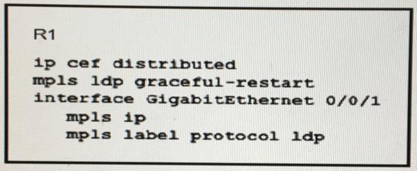
Which effect of this configuration is true?
A. R1 can support a peer that is configured for LDP SSO/NSF as the peer recovers from an outage
B. R1 can failover only to a peer that is configured for LDP SSO/NSF
C. R1 can failover to any peer
D. R1 can support a graceful restart operation on the peer, even if graceful restart is disabled on the peer
Explanation
The configuration command mpls ldp graceful-restart enables the Label Distribution Protocol (LDP) Graceful Restart mechanism on the router.
Why Option A Is Correct
When LDP graceful restart is enabled, R1 can preserve its MPLS forwarding state and assist a neighboring peer configured with Nonstop Forwarding / Stateful Switchover (NSF/SSO) during a control plane restart or outage recovery, preventing traffic disruption.
Why Option B Is Incorrect
R1 can establish standard LDP sessions and interoperate with any compliant LDP peer, not only peers configured with LDP SSO/NSF.
Why Option C Is Incorrect
Failover behavior and graceful restart capabilities depend heavily on peer negotiations and capability advertisements. LDP graceful restart must be supported or negotiated between peers, rather than arbitrarily failing over to any peer.
Why Option D Is Incorrect
Graceful restart operations require mutual capability advertisement during the LDP initialization phase. If graceful restart is disabled on the peer, the peer will not advertise the graceful restart TLV, preventing the feature from functioning as intended with that neighbor.
Reference
Cisco Official Documentation: Implementing and Operating Cisco Service Provider Network Core Technologies (SPCOR 350-501) — MPLS LDP Graceful Restart and High Availability Configuration Guide.
Refer to the exhibit.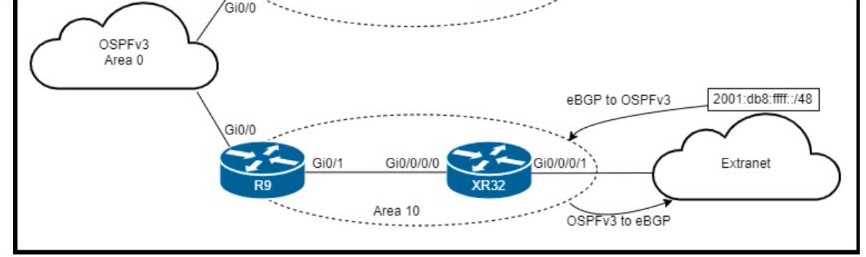
An engineer is updating this network to meet these conditions:
• Area 10 will receive inter-area routes and support mutual redistribution of external routes
with the extranet.
• The ::/0 route is prohibited in Area 10.
• Area 11 will receive only the ::/0 route from the ABR.
• External route redistribution is not supported in Area 11.
• The ABR in Area 11 will advertise no interarea routes.
Which two configurations must be performed to meet the requirements? (Choose two.)
A. Configure area 11 as nssa no-summary on R7 and as nssa on XR31.
B. Configure area 10 as stub on R9 and XR32.
C. Configure area 11 as stub no-summary on R7 and as stub on XR31.
D. Configure area 11 as nssa default-information-originate on R7 and as nssa on XR31.
E. Configure area 10 as nssa on R9 and XR
E. Configure area 10 as nssa on R9 and XR
Explanation
Area 10 must receive interarea routes and support mutual redistribution of external routes with the extranet. This means Area 10 cannot be a stub or totally stubby area, because those area types block external routes (Type 5 LSAs). The correct area type for supporting external route redistribution while still receiving interarea routes is NSSA (Not-So-Stubby Area), which allows Type 7 LSAs to carry external routes. Therefore, Area 10 must be configured as `nssa` on both R9 and XR32.
Area 11 must receive only the default route (`::/0`) from the ABR, must not support external route redistribution, and the ABR must not advertise any interarea routes. This describes a totally stubby area, which is configured with `stub no-summary` on the ABR and `stub` on the internal router. The `no-summary` keyword on the ABR blocks all interarea (Type 3) LSAs except the default route, satisfying all requirements for Area 11.
This makes options C and E the correct answers.
Why the other options are incorrect:
A. Configure area 11 as nssa no-summary on R7 and as nssa on XR31 – NSSA allows external route redistribution via Type 7 LSAs, which violates the requirement that external route redistribution is not supported in Area 11. The correct type for Area 11 is totally stubby, not NSSA.
B. Configure area 10 as stub on R9 and XR32 – A stub area blocks external routes (Type 5 LSAs), which violates the requirement that Area 10 must support mutual redistribution of external routes with the extranet.
D. Configure area 11 as nssa default-information-originate on R7 and as nssa on XR31 – NSSA allows external redistribution, which is prohibited in Area 11. Additionally, `default-information-originate` in NSSA generates a Type 7 default route, but the requirement calls for the totally stubby behavior where only the default route is received and no external redistribution is supported.
Reference:
RFC 3101 – The OSPF Not-So-Stubby Area (NSSA) Option; RFC 5340 – OSPF for IPv6 (OSPFv3); Cisco IOS XR Routing Configuration Guide – Implementing OSPFv3: Stub and NSSA Areas; Cisco 350-501 SPCOR Official Cert Guide, OSPF chapter.
Refer to the exhibit:
Which information is provided for traceback analysis when this configuration is applied?
A. BGP version
B. packet size distribution
C. source interface
D. IP sub flow cache
Explanation
The exhibit shows a NetFlow configuration using `ip flow-export version 9` with `ip flow ingress` on the interface. NetFlow version 9 is a flexible, template-based export format that supports a wide range of fields, including those needed for traceback analysis. Traceback analysis is used to identify the source and path of attack traffic, and it requires detailed flow information such as source and destination IP addresses, source and destination ports, protocol, TCP flags, andsource interface. The `ip flow ingress` command captures flow data on the ingress direction of the interface, and NetFlow v9 includes the input interface (source interface) as one of its supported fields, which is essential for traceback analysis to determine where traffic entered the router. This makes option C the correct answer.
Why the other options are incorrect:
A. BGP version
– NetFlow does not report the BGP version as part of its flow records. BGP-related fields such as AS numbers can be included, but the BGP version itself is not a NetFlow field used for traceback analysis.
B. Packet size distribution
– NetFlow records include packet and byte counts, not packet size distribution histograms. Packet size distribution is not a standard NetFlow field for traceback.
D. IP sub flow cache
– The sub flow cache is an internal memory structure used by NetFlow to store flow entries before they are exported; it is not information provided for traceback analysis.
Reference:
Cisco IOS NetFlow Configuration Guide – NetFlow Version 9 Field Types and Traceback Analysis; RFC 3954 – Cisco Systems NetFlow Services Export Version 9; Cisco 350-501 SPCOR Official Cert Guide, Network Assurance section.
Refer to the exhibit: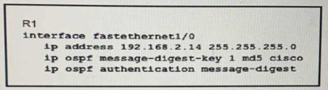
Which condition must be met by the OSPF peer of router R1 before the two devices can
establish communication?
A. The interface on the OSPF peer must use the same key ID and key value as the configured interface
B. The interface on the OSPF peer may have a different key ID, but it must use the same key value as the configured interface
C. The OSPF peer must be configured as an OSPF stub router
D. The OSPF peer must use clear-text authentication
Explanation
The exhibit shows R1 configured with `ip ospf message-digest-key 1 md5 cisco` and `ip ospf authentication message-digest` on FastEthernet1/0. For two OSPF routers to establish an adjacency using MD5 authentication, both routers must be configured with matching authentication parameters. Specifically, the key ID, the key value (password), and the authentication type (MD5) must match on both sides. If the key ID or key value differs, the MD5 hash computed by each router will not match, and the OSPF hello packets will fail authentication, preventing the adjacency from forming. Therefore, the OSPF peer must use the same key ID and key value as configured on R1. This makes option A the correct answer.
Why the other options are incorrect:
B. The interface on the OSPF peer may have a different key ID, but it must use the same key value as the configured interface – The key ID is part of the authentication information included in the OSPF packet. If the key IDs differ, the receiving router will not be able to look up the correct key to validate the MD5 digest, and authentication will fail. Both the key ID and key value must match.
C. The OSPF peer must be configured as an OSPF stub router – The stub router designation is unrelated to authentication. It affects the router's behavior in the SPF calculation but does not influence whether an adjacency can be established with MD5 authentication.
D. The OSPF peer must use clear-text authentication – R1 is configured for MD5 authentication, not clear-text authentication. The authentication type must match on both sides, so the peer must also use MD5, not clear-text.
Reference:
RFC 2328 – OSPF Version 2 (Authentication); RFC 5709 – OSPFv2 HMAC-SHA Cryptographic Authentication; Cisco IOS XR Routing Configuration Guide – Implementing OSPF: Authentication; Cisco 350-501 SPCOR Official Cert Guide, OSPF chapter.
| Page 11 out of 55 Pages |