• 4.9/5.0
  • 547 Questions
  • Updated on: 12-Oct-2026
  • Implementing and Operating Cisco Service Provider Network Core Technologies (350-501 SPCOR)
  • 25475 Prepared

Free Cisco 350-501 Practice Questions 2026 | Implementing and Operating Cisco Service Provider Network Core Technologies (350-501 SPCOR)


Which OoS model allows hosts to report their OoS needs to the network?

A. DiffServ

B. CB-WFQ

C. IntServ

D. MQC

C.   IntServ

Explanation

The Integrated Services (IntServ) QoS model allows hosts to signal their QoS requirements to the network before sending data, using a signaling protocol such as RSVP. The host requests a specific level of service (for example, guaranteed bandwidth or bounded delay), and the network reserves resources along the path to meet that request. This explicit signaling from hosts to the network is the defining characteristic of IntServ. This makes option C the correct answer.

Why the other options are incorrect:

A. DiffServ
Differentiated Services classifies and marks traffic into behavior aggregates and applies per-hop behaviors based on those markings. It does not provide a mechanism for individual hosts to signal their QoS needs to the network.

B. CB-WFQ
Class-Based Weighted Fair Queuing is a queuing mechanism used within a router to provide differentiated scheduling for different traffic classes. It is not a QoS model for host-to-network signaling.

D. MQC
The Modular QoS CLI is a Cisco configuration framework for defining and applying QoS policies (class maps, policy maps, service policies). It is a configuration tool, not a QoS model for host signaling.

Reference:
RFC 1633 – Integrated Services in the Internet Architecture: an Overview; RFC 2475 – An Architecture for Differentiated Services; Cisco 350-501 SPCOR Official Cert Guide, QoS section.

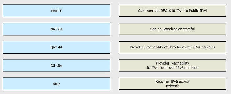
Drag and drop the functionalities from the left onto the correct target fields on the righ


Explanation:

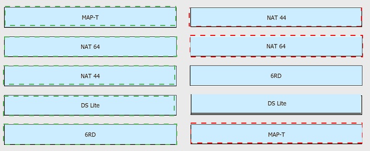
The exhibit requires matching each IPv6 transition technology with its correct functionality. NAT44 translates RFC1918 private IPv4 addresses to public IPv4 addresses. NAT64 can operate in either stateless or stateful mode to translate between IPv6 and IPv4. 6RD (IPv6 Rapid Deployment) provides reachability to IPv4 hosts over IPv6 domains by encapsulating IPv4 traffic within IPv6. DS Lite (Dual-Stack Lite) requires an IPv6 access network to tunnel IPv4 traffic over the IPv6 infrastructure. MAP-T provides reachability of IPv6 hosts over IPv4 domains using stateless IPv4-to-IPv6 mapping and translation. This makes the correct matches as follows:

NAT44 → Can translate RFC1918 IPv4 to Public IPv4
NAT64 → Can be Stateless or stateful
6RD → Provides reachability to IPv4 host over IPv6 domains
DS Lite → Requires IPv6 access network
MAP-T → Provides reachability of IPv6 host over IPv4 domains

Why the other pairings are incorrect:

Matching MAP-T with the "Can translate RFC1918 IPv4 to Public IPv4" description is incorrect because that describes NAT44, not MAP-T. MAP-T is a stateless IPv4-to-IPv6 mapping and translation mechanism that allows IPv6 hosts to communicate with IPv4 resources.

Matching NAT64 with the "Provides reachability of IPv6 host over IPv4 domains" description is incorrect because that is the role of MAP-T. NAT64 allows IPv6-only hosts to reach IPv4 servers by translating IPv6 packets to IPv4, which is the opposite direction.

Matching DS Lite with the "Provides reachability to IPv4 host over IPv6 domains" description is incorrect because that describes 6RD. DS Lite requires an IPv6 access network and uses IPv4-in-IPv6 tunneling with carrier-grade NAT.

Matching 6RD with the "Requires IPv6 access network" description is incorrect because 6RD provides IPv6 connectivity over an existing IPv4 access network, not the other way around. DS Lite is the technology that requires an IPv6 access network.

Reference:
RFC 2663 – IP Network Address Translator (NAT) Terminology and Considerations; RFC 6146 – Stateful NAT64; RFC 5569 – IPv6 Rapid Deployment on IPv4 Infrastructures (6rd); RFC 6333 – Dual-Stack Lite Broadband Deployments Following IPv4 Exhaustion; RFC 7599 – Mapping of Address and Port using Translation (MAP-T); Cisco 350-501 SPCOR Official Cert Guide, Architecture and Services section.

Which feature will an operator use while implementing MPLS TE on customer's network, to prevent an LSP from using any overseas inks?

A. bandwidth

B. affinity

C. explicit path

D. SLRG

B.   affinity

Explanation

To prevent an MPLS TE LSP from using any overseas links, the operator should use affinity (also called administrative groups or link coloring). Affinity allows the network operator to assign attributes (colors) to links based on characteristics such as geographic location, and then configure the TE tunnel to include or exclude links with specific attributes. By marking overseas links with a particular affinity bit and configuring the tunnel's affinity to exclude that bit, the LSP will avoid those links. This makes option B the correct answer.

Why the other options are incorrect:

A. Bandwidth
Bandwidth reservation ensures the LSP has enough capacity on the links it uses, but it does not control which links the LSP traverses based on geographic or administrative constraints.

C. Explicit path
An explicit path can manually specify the hops for the LSP, which could be used to avoid overseas links. However, the more scalable and common mechanism for constraining LSPs based on link attributes such as geographic location is affinity. Explicit paths are static and require maintenance, while affinity dynamically excludes links based on attributes.

D. SLRG
Shared Risk Link Group (SRLG) is used to identify links that share a common risk of failure (for example, fibers in the same conduit). It is used for path diversity and disjointness, not for avoiding overseas links.

Reference:
RFC 3209 – RSVP-TE: Extensions to RSVP for LSP Tunnels; RFC 2702 – Requirements for Traffic Engineering Over MPLS; Cisco IOS XR MPLS Configuration Guide – Implementing MPLS Traffic Engineering: Affinity and Administrative Groups; Cisco 350-501 SPCOR Official Cert Guide, MPLS Traffic Engineering chapter.

What Is the primary role of Ansible In a network?

A. It is used as a debugging tool for connectivity issues between the DMZ and an enterprise intranet.

B. It Is used to diagnose Layer 11ssues In data centers that span more than one city block.

C. It is used to deploy IPv6 configuration is networks That are dual slack.

D. It is used as a network automation provisioning and configuration to

D.   It is used as a network automation provisioning and configuration to

Explanation

Ansible is an open-source automation tool whose primary role in a network is to automate provisioning, configuration management, and orchestration of network devices. It uses agentless SSH-based connections and YAML-based playbooks to push configuration changes, deploy services, and maintain consistent device states across multivendor environments. This makes option D the correct answer.

Why the other options are incorrect:

A. It is used as a debugging tool for connectivity issues between the DMZ and an enterprise intranet
Ansible is not a debugging or connectivity troubleshooting tool. It automates configuration and provisioning, not packet-level diagnostics.

B. It is used to diagnose Layer 1 issues in data centers that span more than one city block
Ansible does not diagnose physical-layer issues. Layer 1 troubleshooting is done with physical testing and interface diagnostics, not automation playbooks.

C. It is used to deploy IPv6 configuration in networks that are dual stack
While Ansible can be used to deploy IPv6 configurations as part of a broader automation strategy, this is only one specific use case. The primary role of Ansible is general network automation and configuration management, not IPv6 deployment specifically.

Reference:
Red Hat Ansible Documentation – Network Automation Overview; Cisco 350-501 SPCOR Official Cert Guide, Automation and Assurance section.

A network team has failed to implement IS-IS multitopology. What is the reason for it?

A. The router did not support VRFs.

B. The routing process did not support extended metrics.

C. The router did not have Cisco Discovery Protocol and Cisco Express Forwarding disabled.

D. The routing process supported Level 1 only.

B.   The routing process did not support extended metrics.

Explanation

IS-IS multitopology (MT) requires support for extended metrics (also called wide metrics) because the MT TLVs carry metric information that exceeds the narrow metric range. If the routing process does not support extended metrics, the router cannot advertise or process the MT TLVs, and multitopology fails to operate. This is a fundamental requirement for IS-IS MT, because the standard narrow metric format (6-bit per metric) is insufficient for the MT extensions defined in RFC 5120. This makes option B the correct answer.

Why the other options are incorrect:

A. The router did not support VRFs
IS-IS multitopology is not dependent on VRF support. VRFs are a separate concept used in MPLS L3VPN, and MT can be deployed independently.

C. The router did not have Cisco Discovery Protocol and Cisco Express Forwarding disabled
CDP and CEF are unrelated to IS-IS multitopology operation. Disabling or enabling them does not affect MT support.

D. The routing process supported Level 1 only
IS-IS multitopology can operate at Level 1, Level 2, or both. A Level 1-only process can still support MT as long as the extended metric capability is present. This is not the reason for failure.

Reference:
RFC 5120 – M-ISIS: Multi Topology (MT) Routing in Intermediate System to Intermediate Systems (IS-ISs); Cisco IOS XR Routing Configuration Guide – Implementing IS-IS: Multi-Topology Support; Cisco 350-501 SPCOR Official Cert Guide, IS-IS chapter.

When configuring traffic engineering tunnels in Cisco MPLS core network, you see the traffic is not taking the expected path in the core.
Which command do you use to quickly check path of a TE tunnel?

A. Traceroute mpls ipv4 -tunnel destination

B. Ping

C. show mpls traffic-engineering tunnels

D. traceroute

C.   show mpls traffic-engineering tunnels

Explanation

To quickly check the actual path that an MPLS TE tunnel is taking through the core network, the correct command is `show mpls traffic-engineering tunnels`. This command displays detailed information about the TE tunnel, including its operational state, the path it is using (explicit or dynamic), the outgoing interface, and the next-hop information. It allows the operator to verify whether the tunnel is following the expected path or if it has been rerouted due to a constraint or failure. This makes option C the correct answer.

Why the other options are incorrect:

A. Traceroute mpls ipv4 -tunnel destination
This syntax is not a valid Cisco command for checking TE tunnel paths. MPLS LSP traceroute uses `traceroute mpls ipv4 `, but it does not use the `-tunnel` keyword in the way shown.

B. Ping <tunnel destination IP>
A standard ping to the tunnel destination only verifies reachability. It does not show the path the TE tunnel is taking through the core, nor does it confirm whether the tunnel is following the expected constrained path.

D. traceroute <tunnel destination IP>
A standard IP traceroute to the tunnel destination follows the IP routing path, not the MPLS TE tunnel path. It does not reveal which links the TE tunnel is using.

Reference:
Cisco IOS XR MPLS Configuration Guide – Implementing MPLS Traffic Engineering: Verifying TE Tunnel Paths; RFC 3209 – RSVP-TE: Extensions to RSVP for LSP Tunnels; Cisco 350-501 SPCOR Official Cert Guide, MPLS Traffic Engineering chapter.

You are configuring MPLS traffic-engineering tunnels in the core.
Which two ways exist for the tunnel path across the core? (Choose two )

A. Tunnel links inherit IGP metrics by default unless overridden

B. Tunnels can be configured with dynamic path or explicitly defined path

C. A zero bandwidth tunnel is not a valid option

D. The bandwidth statement creates a "hard" reservation on the link-The dynamic path option is supported only with IS-IS

A.   Tunnel links inherit IGP metrics by default unless overridden
B.   Tunnels can be configured with dynamic path or explicitly defined path

Explanation

When configuring MPLS TE tunnels, there are two fundamental ways to define the path the tunnel takes across the core: a dynamic path, where the headend router uses CSPF (Constrained Shortest Path First) to automatically compute the path based on the TE topology database and constraints, or an explicitly defined path, where the network operator manually specifies the hops (strict or loose) that the tunnel must follow. These are the two supported path options for MPLS TE tunnels. This makes option B the correct answer.

The second correct statement is that tunnel links inherit IGP metrics by default unless overridden. MPLS TE uses the IGP metric as the default TE metric for links. If the operator does not configure a separate TE metric on an interface, the tunnel path computation uses the IGP metric. The operator can override this by configuring a TE metric with `mpls traffic-eng metric ` on the interface. This makes option A the correct answer.

Why the other options are incorrect:

C. A zero bandwidth tunnel is not a valid option
A zero bandwidth tunnel is valid and is commonly used for autoroute announcements and forwarding adjacencies where no bandwidth reservation is required. The tunnel can be configured with `bandwidth 0`.

D. The bandwidth statement creates a "hard" reservation on the link. The dynamic path option is supported only with IS-IS
The bandwidth statement does create a reservation, but this statement also incorrectly claims that the dynamic path option is supported only with IS-IS. Dynamic path computation (CSPF) is supported with both OSPF and IS-IS as long as TE extensions are enabled.

Reference:
RFC 3209 – RSVP-TE: Extensions to RSVP for LSP Tunnels; RFC 3630 – Traffic Engineering (TE) Extensions to OSPF Version 2; RFC 5305 – IS-IS Extensions for Traffic Engineering; Cisco IOS XR MPLS Configuration Guide – Implementing MPLS Traffic Engineering; Cisco 350-501 SPCOR Official Cert Guide, MPLS Traffic Engineering chapter.

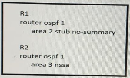
Refer to the exhibit

In which way does router R1 operate differently than router R2?

A. R1 sends LSA type 2 only, while R2 sends type 1 and type 7 LSAs

B. R1 sends LSA types 1 and 2, while R2 sends type 1. 2. and 7 LSAs

C. R1 sends LSA type 2 only and R2 sends LSA type 1 only

D. R1 sends LSA types 5 and 7, while R2 sends type 1, 2, and 7 LSAs

B.   R1 sends LSA types 1 and 2, while R2 sends type 1. 2. and 7 LSAs

Explanation

R1 is configured with `area 2 stub no-summary`, which makes it a totally stubby area border router (ABR). In a totally stubby area, the ABR blocks Type 3 (interarea), Type 4, and Type 5 LSAs, allowing only a default route into the area. Within area 2, R1 still generates Type 1 (router) and Type 2 (network) LSAs as part of normal OSPF operation, but it does not send Type 5 external LSAs. R2 is configured with `area 3 nssa`, making it an NSSA ABR. In an NSSA, Type 5 external LSAs are not allowed, but the ABR can translate Type 7 LSAs from the NSSA into Type 5 LSAs for other areas. R2 also generates Type 1 and Type 2 LSAs within its area and Type 7 LSAs for redistributed external routes. Comparing the two, R1 sends Type 1 and 2 LSAs while R2 sends Type 1, 2, and 7 LSAs. This makes option B the correct answer.

Why the other options are incorrect:

A. R1 sends LSA type 2 only, while R2 sends type 1 and type 7 LSAs
R1 does not send only Type 2 LSAs; it sends Type 1 and Type 2 LSAs. R2 sends Type 1, 2, and 7 LSAs, not just Type 1 and 7.

C. R1 sends LSA type 2 only and R2 sends LSA type 1 only
Neither router sends only one LSA type. Both routers generate multiple LSA types as part of normal OSPF operation.

D. R1 sends LSA types 5 and 7, while R2 sends type 1, 2, and 7 LSAs
R1 is in a totally stubby area and does not send Type 5 or Type 7 LSAs. R2 is in an NSSA and sends Type 1, 2, and 7 LSAs, but R1 does not send Type 5 or 7.

Reference:
RFC 2328 – OSPF Version 2; RFC 3101 – The OSPF Not-So-Stubby Area (NSSA) Option; Cisco IOS XR Routing Configuration Guide – Implementing OSPF: Stub and NSSA Areas; Cisco 350-501 SPCOR Official Cert Guide, OSPF chapter.

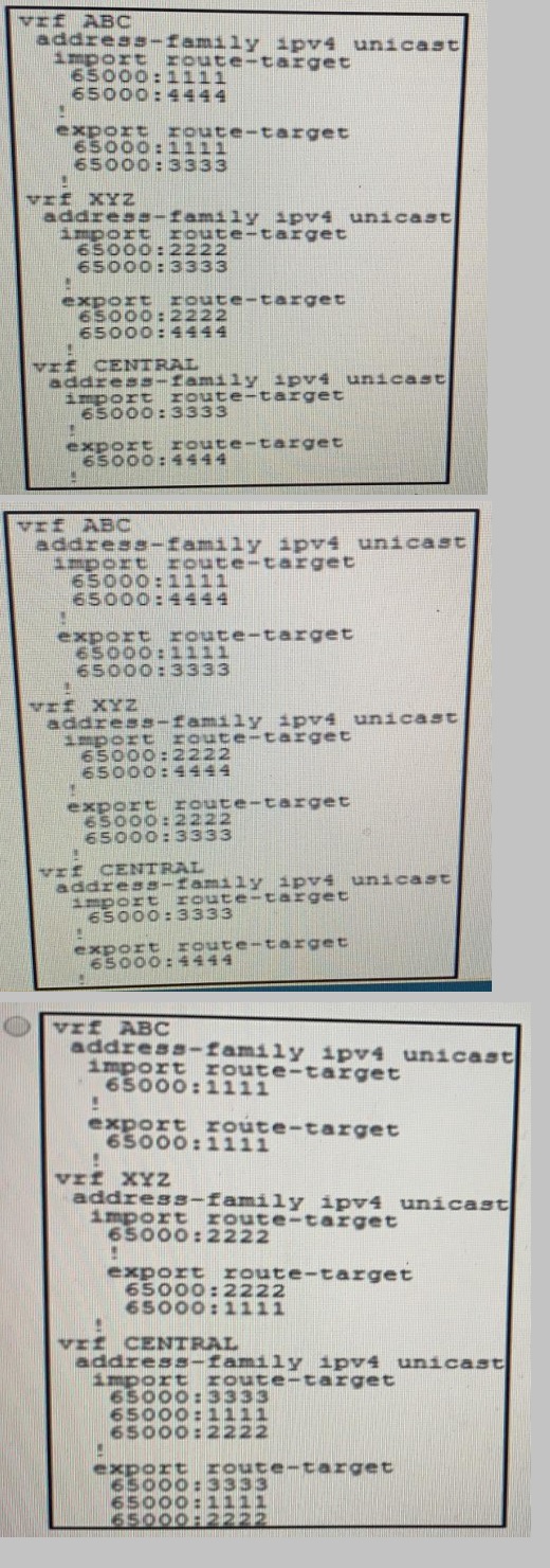
An engineer is setting up overlapping VPNs to allow VRF ABC and XYZ to communicate
with VRF CENTRAL but wants to make sure that VRF ABC and XYZ cannot communicate.
Which configuration accomplishes these objectives?
A. Option A

B. Option B

C. Option C

D. Option D

B.   Option B

Explanation

R1 is configured with `area 2 stub no-summary`, which makes it a totally stubby area border router (ABR). In a totally stubby area, the ABR blocks Type 3 (interarea), Type 4, and Type 5 LSAs, allowing only a default route into the area. Within area 2, R1 still generates Type 1 (router) and Type 2 (network) LSAs as part of normal OSPF operation, but it does not send Type 5 external LSAs. R2 is configured with `area 3 nssa`, making it an NSSA ABR. In an NSSA, Type 5 external LSAs are not allowed, but the ABR can translate Type 7 LSAs from the NSSA into Type 5 LSAs for other areas. R2 also generates Type 1 and Type 2 LSAs within its area and Type 7 LSAs for redistributed external routes. Comparing the two, R1 sends Type 1 and 2 LSAs while R2 sends Type 1, 2, and 7 LSAs. This makes option B the correct answer.

Why the other options are incorrect:

A. R1 sends LSA type 2 only, while R2 sends type 1 and type 7 LSAs
R1 does not send only Type 2 LSAs; it sends Type 1 and Type 2 LSAs. R2 sends Type 1, 2, and 7 LSAs, not just Type 1 and 7.

C. R1 sends LSA type 2 only and R2 sends LSA type 1 only
Neither router sends only one LSA type. Both routers generate multiple LSA types as part of normal OSPF operation.

D. R1 sends LSA types 5 and 7, while R2 sends type 1, 2, and 7 LSAs
R1 is in a totally stubby area and does not send Type 5 or Type 7 LSAs. R2 is in an NSSA and sends Type 1, 2, and 7 LSAs, but R1 does not send Type 5 or 7.

Reference:
RFC 2328 – OSPF Version 2; RFC 3101 – The OSPF Not-So-Stubby Area (NSSA) Option; Cisco IOS XR Routing Configuration Guide – Implementing OSPF: Stub and NSSA Areas; Cisco 350-501 SPCOR Official Cert Guide, OSPF chapter.

Refer to the exhibit.
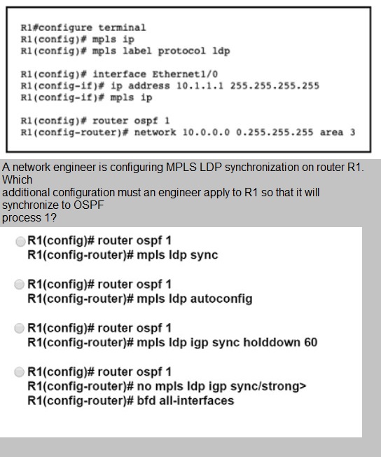
A. Option A

B. Option B

C. Option C

D. Option D

A.   Option A

Explanation

The exhibit shows R1 with global MPLS LDP configuration and OSPF process 1 configured, but LDP-IGP synchronization is not yet enabled. To make R1 synchronize LDP with the OSPF process, the engineer must enter `router ospf 1` configuration mode and issue the `mpls ldp sync` command. This command enables LDP-IGP synchronization for OSPF, ensuring that OSPF does not advertise the link until LDP has converged and label bindings are established, preventing traffic blackholing. This makes option A the correct answer.

Why the other options are incorrect:

B. R1(config-router)# mpls ldp autoconfig
The `mpls ldp autoconfig` command enables LDP on all interfaces participating in the IGP, but it does not enable LDP-IGP synchronization. It is a different feature that automatically enables LDP on IGP interfaces.

C. R1(config-router)# mpls ldp igp sync holddown 60
This command configures the holddown timer for LDP-IGP synchronization, but it does not enable the synchronization feature itself. The `mpls ldp sync` command is still required first.

D. R1(config-router)# no mpls ldp igp sync
This command disables LDP-IGP synchronization, which is the opposite of what is required.

Reference:
Cisco IOS XR MPLS Configuration Guide – Implementing LDP: LDP-IGP Synchronization; RFC 5443 – LDP IGP Synchronization; Cisco 350-501 SPCOR Official Cert Guide, MPLS chapter.

Page 16 out of 55 Pages