- 4.9/5.0
- 547 Questions
- Updated on: 12-Oct-2026
- Implementing and Operating Cisco Service Provider Network Core Technologies (350-501 SPCOR)
- 25475 Prepared
Free Cisco 350-501 Practice Questions 2026 | Implementing and Operating Cisco Service Provider Network Core Technologies (350-501 SPCOR)
Refer to the exhibit: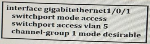
An engineer is preparing to implement link aggregation configuration.
Which statement al about this configuration is true?
A. The switch port actively sends packets to negotiate an EtherChannel using PAgP
B. The switch port accepts LACP and PAgP packets from a connected peer and negotiate an EtherChannel using the common EtherChannel mode.
C. The switch port passively negotiates an EtherChannel if it receives PAgP packets from a connected peer
D. The switch port negotiates an EtherChannel if it receives LACP packets from a connected peer
Explanation
The exhibit shows `channel-group 1 mode desirable` on the interface. In Cisco IOS, the `desirable` mode is a PAgP (Port Aggregation Protocol) mode that actively sends PAgP packets to negotiate an EtherChannel with the connected peer. The `desirable` mode is not passive; it actively initiates the negotiation. This makes option A the correct answer.
Why the other options are incorrect:
B. The switch port accepts LACP and PAgP packets from a connected peer and negotiates an EtherChannel using the common EtherChannel mode
The `desirable` mode is specific to PAgP and does not accept LACP packets. LACP uses `active` or `passive` modes, not `desirable`.
C. The switch port passively negotiates an EtherChannel if it receives PAgP packets from a connected peer
Passive negotiation using PAgP is the `auto` mode, not `desirable`. The `desirable` mode actively initiates negotiation.
D. The switch port negotiates an EtherChannel if it receives LACP packets from a connected peer
The `desirable` mode uses PAgP, not LACP. LACP negotiation would require `active` or `passive` mode.
Reference:
Cisco IOS XR Interface and Hardware Component Configuration Guide – Configuring Link Bundling: PAgP and LACP Modes; IEEE 802.3ad – Link Aggregation; Cisco 350-501 SPCOR Official Cert Guide, Network Assurance section.
Drag and drop the NAT64 descriptions from the left onto the correct NAT64 types on the
right.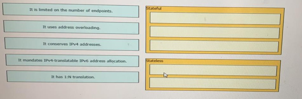
Explanation:
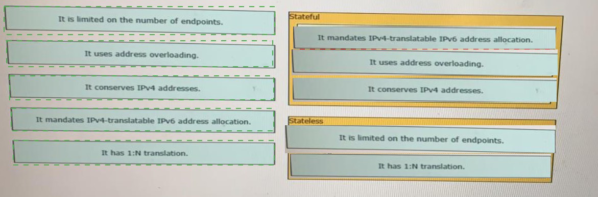
The exhibit requires matching each NAT64 description to the correct NAT64 type: Stateful or Stateless. Stateful NAT64 maintains translation state for each session and uses address overloading, allowing multiple IPv6 hosts to share a single IPv4 address (1:N translation), which conserves IPv4 addresses. It also mandates IPv4-translatable IPv6 address allocation to ensure proper mapping. Stateless NAT64 does not maintain per-session state and has a 1:1 mapping between IPv6 and IPv4 addresses, which limits it on the number of endpoints and does not conserve IPv4 addresses through overloading. This makes the correct matches as follows:
Stateful → It mandates IPv4-translatable IPv6 address allocation.
Stateful → It uses address overloading.
Stateful → It conserves IPv4 addresses.
Stateless → It is limited on the number of endpoints.
Stateless → It has 1:N translation.
Why the other pairings are incorrect:
Matching "It is limited on the number of endpoints" with Stateful is incorrect because Stateful NAT64 uses address overloading to allow many IPv6 hosts to share few IPv4 addresses, so it is not limited in the same way as Stateless.
Matching "It uses address overloading" with Stateless is incorrect because Stateless NAT64 uses a 1:1 address mapping and does not perform overloading.
Matching "It conserves IPv4 addresses" with Stateless is incorrect because Stateless NAT64 requires a unique IPv4 address for each IPv6 endpoint, so it does not conserve IPv4 addresses through sharing.
Matching "It mandates IPv4-translatable IPv6 address allocation" with Stateless is incorrect because this requirement applies to Stateful NAT64 (RFC 6146), which uses IPv4-translatable addresses for the mapping.
Matching "It has 1:N translation" with Stateless is incorrect because Stateless NAT64 performs 1:1 translation, not 1:N. Stateful NAT64 is the one that supports 1:N translation through overloading.
Reference:
RFC 6146 – Stateful NAT64:Network Address and Protocol Translation from IPv6 Clients to IPv4 Servers; RFC 6145 – IP/ICMP Translation Algorithm (Stateless); Cisco 350-501 SPCOR Official Cert Guide, Architecture and Services section.
Refer to the exhibit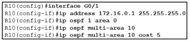
A network engineer is implementing OSPF multiarea. Which command on interface GO/1
resolves adjacency issues in the new area?
A. ip ospf network broadcast
B. ip ospf network point-to-point
C. ip ospf network non-broadcast
D. ip ospf network point-to-multipoint
Explanation
The exhibit shows interface G0/1 configured with `ip ospf 1 area 0` and `ip ospf multi-area 10`. The `ip ospf multi-area` command is used in OSPF multiarea configurations to allow an interface to participate in multiple areas, typically for multiarea adjacencies. When an interface is configured with multi-area, it is commonly used on point-to-point links to form adjacencies in multiple areas. However, by default, an Ethernet interface operates as a broadcast network type, which can cause adjacency issues in a multiarea configuration because broadcast networks require DR/BDR election and are not suitable for multiarea adjacencies. Changing the interface to `ip ospf network point-to-point` eliminates the DR/BDR election and allows the multiarea adjacency to form correctly. This makes option B the correct answer.
Why the other options are incorrect:
A. `ip ospf network broadcast`
Broadcast is the default network type on Ethernet interfaces, so this command would not change anything and would not resolve the adjacency issues in the multiarea configuration.
C. `ip ospf network non-broadcast`
The non-broadcast network type requires manual neighbor configuration and is used for NBMA networks such as Frame Relay. It is not the appropriate choice for resolving multiarea adjacency issues on an Ethernet link.
D. `ip ospf network point-to-multipoint`
Point-to-multipoint is used for hub-and-spoke topologies and does not require DR/BDR election, but it is not the standard choice for a point-to-point multiarea adjacency. Point-to-point is the more appropriate and commonly used network type for this scenario.
Reference:
RFC 2328 – OSPF Version 2; Cisco IOS XR Routing Configuration Guide – Implementing OSPF: Multiarea Adjacencies and Network Types; Cisco 350-501 SPCOR Official Cert Guide, OSPF chapter.
Refer to the exhibit:
With which router does IOSXRV-1 have LDP session protection capability enabled but
session hold up is not active?
A. 192.168.0.1
B. 192.168.0.3
C. 192.168.0.4
D. 192.168.0.5
Explanation
The output shows targeted hello adjacencies, which appear as entries starting with `Tgt:`. The `Tgt:192.168.0.5` entry shows a dash (`-`) in the Peer LDP Id column and `N` in the Holdtime column, indicating that the targeted hello adjacency exists but the LDP session is not currently active. The other targeted entries (`Tgt:192.168.0.1` and `Tgt:192.168.0.3`) show peer LDP IDs and `Y` in the Holdtime column, meaning their sessions are active. Therefore, the router with which IOSXRV-1 has LDP session protection capability enabled but no active session is **192.168.0.5**. This makes option D the correct answer.
Why the other options are incorrect:
A. 192.168.0.1
The `Tgt:192.168.0.1` entry shows Peer LDP Id `192.168.0.1:0` and Holdtime `90` with `Y`, indicating an active session.
B. 192.168.0.3
The `Tgt:192.168.0.3` entry shows Peer LDP Id `192.168.0.3:0` and Holdtime `90` with `Y`, indicating an active session.
C. 192.168.0.4
The `Gi0/0/2` entry shows `192.168.0.4:0` with Holdtime `15` and `Y`, indicating an active link-level LDP session, not a session protection scenario.
Reference:
RFC 5036 – LDP Specification; Cisco IOS XR MPLS Configuration Guide – Implementing LDP: Session Protection and Targeted Hellos; Cisco 350-501 SPCOR Official Cert Guide, MPLS chapter.
Refer to the exhibit.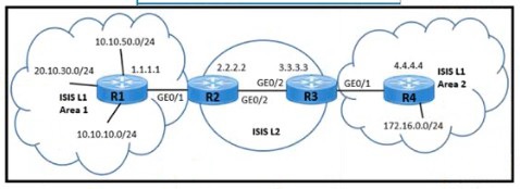
A network engineer must meet these requirements to provide a connects, solution:
The customer connected to Area 2 needs to access the application in Area 1 on
the 10.10.10.0/24 subnet The Customer must not have access to the 20.10 30.0/24 subnet. The service provider must make sure that the Area 2 routing database limits the number of IP addresses in the routing table Which two configurations must be implemented to meet the requirements? (Choose two)
A. Set a tag value of 200 to match the summary address 10.0.0/16 on R2.
B. Set a tag value of 200 to match the summary address 10.0.0.0/16 on R3.
C. Apply the route map for tag 200 and leak Level 2 routes into Level 1 Area 2 on R3
D. Apply the route map for tag 200 and teak Level 2 routes into Level 1 Area 2 on R4.
E. Set a tag value of 200 to match the summary address 10.0.0./16 on R1.
C. Apply the route map for tag 200 and leak Level 2 routes into Level 1 Area 2 on R3
Explanation
To meet the requirements, the customer in Area 2 (IS-IS Level 1) needs access to the `10.10.10.0/24` subnet in Area 1, but must not have access to the `20.10.30.0/24` subnet. Additionally, the routing database in Area 2 must be limited in the number of IP addresses. The solution is to summarize the Area 1 prefixes into a single summary route (`10.0.0.0/16`) on R2, which is the Level 1/Level 2 router connecting Area 1 to the Level 2 backbone, and tag that summary with a value of 200. Then, on R3 (the Level 1/Level 2 router connecting the Level 2 backbone to Area 2), a route map matching tag 200 is applied to leak the tagged Level 2 routes into Level 1 Area 2. This allows only the summarized prefix (which includes `10.10.10.0/24` but not `20.10.30.0/24`) into Area 2, limiting the routing table size and controlling access. This makes options A and C the correct answers.
Why the other options are incorrect:
B. Set a tag value of 200 to match the summary address `10.0.0.0/16` on R3
R3 is the router connecting to Area 2, but the summarization should occur on R2, which is the router connecting Area 1 to the Level 2 backbone. Tagging on R3 would not summarize the Area 1 prefixes before they enter the Level 2 domain.
D. Apply the route map for tag 200 and leak Level 2 routes into Level 1 Area 2 on R4
R4 is entirely within Area 2 (IS-IS L1 Area 2) and is not a Level 1/Level 2 router. Route leaking from Level 2 into Level 1 must be done on the Level 1/Level 2 router, which is R3, not R4.
E. Set a tag value of 200 to match the summary address `10.0.0.0/16` on R1
R1 is within Area 1 and is a Level 1 router. Summarization and tagging for leaking into Area 2 should be done on the Level 1/Level 2 router (R2) that connects Area 1 to the backbone, not on R1.
Reference:
ISO/IEC 10589 – IS-IS for Routing Information Exchange; RFC 5305 – IS-IS Extensions for Traffic Engineering; Cisco IOS XR Routing Configuration Guide – Implementing IS-IS: Route Leaking and Summarization; Cisco 350-501 SPCOR Official Cert Guide, IS-IS chapter.
Refer to the exhibit.
A. Option A
B. Option B
C. Option B
D. Option D
Explanation
The requirement is to advertise only `10.16.4.0/24`, `10.16.5.0/24`, and the summarized route `10.16.0.0/21`, while suppressing the more specific `10.16.6.0/24`. The access list `Suppressed` permits `10.16.6.0/24`, and the route map `SuppressMap` matches that access list to identify the prefix to be suppressed. The `aggregate-address` command with `as-set` and `suppress-map` is used to create the summary route and suppress the specified more-specific routes. The correct summary route is `10.16.0.0/21`, which covers `10.16.0.0` through `10.16.7.255`, and the suppress map references the `SuppressMap` route map. Option B uses `aggregate-address 10.16.0.0 255.255.248.0 as-set suppress-map SuppressMap`, which correctly summarizes to /21 and applies the suppress map. This makes option B the correct answer.
Why the other options are incorrect:
A. Option A
It uses a mask of `255.255.252.0`, which is a /22 summary (`10.16.0.0/22`), not the required /21. This would not cover `10.16.4.0/24` and `10.16.5.0/24` within the summary route.
C. Option C
It uses `aggregate-address 10.16.6.0 255.255.255.0`, which summarizes the `10.16.6.0/24` prefix itself instead of creating the required `10.16.0.0/21` summary route.
D. Option D
It uses `aggregate-address 10.16.0.0 255.255.255.0` (a /24 summary), which is incorrect for summarizing `10.16.0.0/21`, and it uses `unSuppressMap` instead of `suppress-map`, which is not valid for suppressing specific prefixes.
Reference:
Cisco IOS XR Routing Configuration Guide – Implementing BGP: Aggregate Address and Suppress Map; RFC 4271 – A Border Gateway Protocol 4 (BGP-4); Cisco 350-501 SPCOR Official Cert Guide, BGP chapter.
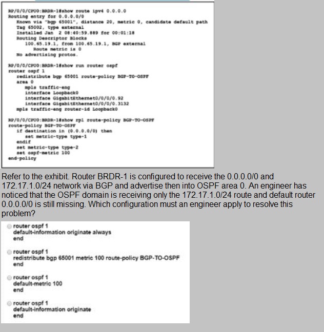
A. Option A
B. Option B
C. Option C
D. Option D
Explanation
The exhibit shows that Router BRDR-1 is configured to redistribute BGP into OSPF with a route policy, and the BGP route table shows the `0.0.0.0/0` default route learned via BGP. However, the default route is not appearing in OSPF Area 0. The issue is that the `redistribute bgp 65001 route-policy BGP-TO-OSPF` command redistributes BGP routes into OSPF as external Type 2 (or Type 1) LSAs, but a default route (`0.0.0.0/0`) is not automatically injected into OSPF just by redistribution unless `default-information originate` is configured. To inject the default route into OSPF, the `default-information originate` command must be used under the OSPF process. Option A uses `default-information originate always`, which injects the default route into OSPF unconditionally, ensuring the `0.0.0.0/0` route is advertised into Area 0. This makes option A the correct answer.
Why the other options are incorrect:
B. Option B
It uses `redistribute bgp 65001 metric 100 route-policy BGP-TO-OSPF`, which redistributes BGP routes with a metric but still does not inject the default route unless the default route is explicitly matched and redistributed. The default route would not be automatically included without `default-information originate`.
C. Option C
It sets `default-metric 100` under OSPF, which changes the metric used for redistributed routes but does not inject a default route into OSPF.
D. Option D
It uses `default-information originate` without the `always` keyword, which only injects the default route if the router already has a default route in its routing table. While this could work in some cases, the `always` keyword in Option A ensures the default route is always advertised regardless of whether a default route exists in the RIB, which is the more reliable solution for this scenario. Option A is the preferred configuration.
Reference:
Cisco IOS XR Routing Configuration Guide – Implementing OSPF: Default Information Originate; RFC 2328 – OSPF Version 2; Cisco 350-501 SPCOR Official Cert Guide, OSPF and BGP chapters.
A network engineer must configure a router for Flexible NetFlow IPFIX export. The IP address of the destination server is 172.17.12.1 The source address must be set to the Loopback0 IPv4 address and exported packets must be set to DSCP CS3. The TTL must be 64 and the transport protocol must be set to UDP with destination port 4739. Which configuration must the engineer apply to the router?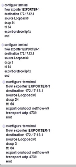
A. Option A
B. Option B
C. Option C
D. Option D
Explanation
The requirement is to configure Flexible NetFlow with IPFIX export. The destination server is `172.17.12.1`, the source must be `Loopback0`, the DSCP must be CS3, the TTL must be `64`, and the transport protocol must be UDP with destination port `4739`. DSCP CS3 corresponds to a decimal value of 24 (CS3 = `011000` binary = 24 decimal). The export protocol must be IPFIX (not NetFlow v9), and the transport must be UDP with port `4739`, which is the standard IPFIX port. Option A correctly configures `destination 172.17.12.1`, `source Loopback0`, `dscp 24` (which is CS3), `ttl 64`, and `export-protocol ipfix`. This makes option A the correct answer.
Why the other options are incorrect:
B. Option B
It uses `dscp 3` instead of `dscp 24`. DSCP 3 is not CS3; CS3 is decimal 24. This is the wrong DSCP value.
C. Option C
It uses `export-protocol netflow-v9` instead of `ipfix`. The requirement specifically states IPFIX export, and the transport port `4739` is the IPFIX port, not the commonly used NetFlow v9 port (`2055`).
D. Option D
It uses both `dscp 3` (incorrect; it should be 24) and `export-protocol netflow-v9` (incorrect; it should be `ipfix`). Both parameters are wrong.
Reference:
RFC 7011 – Specification of the IP Flow Information Export (IPFIX) Protocol; Cisco IOS XR NetFlow Configuration Guide – Configuring Flexible NetFlow and IPFIX Export; Cisco 350-501 SPCOR Official Cert Guide, Network Assurance section.
| Page 18 out of 55 Pages |