- 4.9/5.0
- 547 Questions
- Updated on: 12-Oct-2026
- Implementing and Operating Cisco Service Provider Network Core Technologies (350-501 SPCOR)
- 25475 Prepared
Free Cisco 350-501 Practice Questions 2026 | Implementing and Operating Cisco Service Provider Network Core Technologies (350-501 SPCOR)
Refer to the exhibit.
A. Option A
B. Option B
C. Option C
D. Option D
Explanation
The exhibit shows R2 with interface Ethernet1/0 configured with an IP address (`10.1.1.1/32`). To support MPLS LDP sessions, LDP must be enabled globally and then activated on the interface. Option C correctly configures `mpls ip` globally, `mpls label protocol ldp` globally, and then `mpls ip` on interface Ethernet1/0. The `mpls ip` command on the interface enables LDP on that interface so it can form LDP sessions and exchange label bindings with R1. This makes option C the correct answer.
Why the other options are incorrect:
A. Option A
It enables `mpls label protocol ldp` globally and `mpls bgp forwarding` on the interface. The `mpls bgp forwarding` command is used for BGP labeled unicast (RFC 3107), not for LDP. It does not enable LDP on the interface.
B. Option B
It enables `mpls label protocol ldp` globally but then configures VRF forwarding and OSPF on interface Ethernet1/1, which is not the interface shown in the exhibit. This does not enable LDP on the correct interface.
D. Option D
It enables `mpls label protocol ldp` globally but then configures VRF forwarding and OSPF on Ethernet1/0 instead of enabling MPLS LDP with `mpls ip`. This does not enable LDP on the interface.
Reference:
Cisco IOS XR MPLS Configuration Guide – Implementing LDP: Enabling LDP on Interfaces; RFC 5036 – LDP Specification; Cisco 350-501 SPCOR Official Cert Guide, MPLS chapter.
Refer to the exhibit.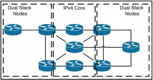
A network operator has two IPv4 and IPv6 dual-stacked network on each side of the IPv4
core network. The operator must be able to provide connectivity between them while using
specific assigned IPv6 space provided from the company IP administrator team. Which
technology should the network operator use to accomplish this goal?
A. 6rd
B. NAT46
C. DS-Lite
D. NAT44
Explanation
The scenario describes two dual-stack IPv6 networks separated by an IPv4-only core network, and the operator needs to provide connectivity between them using specific assigned IPv6 space. This is the classic use case for 6rd (IPv6 Rapid Deployment). 6rd tunnels IPv6 packets over an IPv4 core by encapsulating IPv6 inside IPv4, and it allows the operator to use their own assigned IPv6 prefix rather than a shared one like 6to4. This enables the dual-stack sites to communicate across the IPv4 core using the specific IPv6 address space provided by the company's IP administrator. This makes option A the correct answer.
Why the other options are incorrect:
B. NAT46
NAT46 translates between IPv4 and IPv6, allowing IPv6-only hosts to communicate with IPv4-only hosts. However, in this scenario, the sites are dual-stack and need IPv6 connectivity across an IPv4 core, not translation between IPv4 and IPv6 hosts.
C. DS-Lite
DS-Lite (Dual-Stack Lite) is used to provide IPv4 connectivity to IPv4 hosts over an IPv6 access network. It is the opposite of what is needed here, where IPv6 connectivity must traverse an IPv4 core.
D. NAT44
NAT44 translates between IPv4 addresses (RFC 1918 to public IPv4). It does not provide IPv6 connectivity and is unrelated to the requirement.
Reference:
RFC 5569 – IPv6 Rapid Deployment on IPv4 Infrastructures (6rd); RFC 5969 – IPv6 Rapid Deployment on IPv4 Infrastructures (6rd) – Protocol Specification; Cisco 350-501 SPCOR Official Cert Guide, Architecture and Services section.
Refer to the exhibit.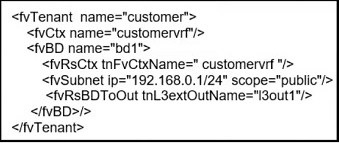
What does this REST API script configure?
A. application profile
B. VRF
C. public community string for SNMP
D. interface with IP address 192.168.0.1
Explanation
The exhibit shows a REST API script using the Cisco ACI managed object model. The script creates an `fvTenant` named "customer", an `fvCtx` named "customervrf" (which is a VRF instance), an `fvBD` named "bd1" (a bridge domain), an `fvSubnet` with IP `192.168.0.1/24`, and an `fvRsBDToOut` that associates the bridge domain with an L3Out named "l3out1". The central object being configured is the VRF (`fvCtx`), which is the Layer 3 context for the tenant. While the script also creates a bridge domain and subnet, the primary managed object being defined is the VRF (`fvCtx`), which provides Layer 3 isolation. This makes option B the correct answer.
Why the other options are incorrect:
A. Application profile
An application profile in ACI is configured using the `fvAp` managed object, which is not present in this script. The script configures a tenant, VRF, and bridge domain, not an application profile.
C. Public community string for SNMP
SNMP community strings are not configured via the ACI tenant managed objects shown here. The script deals with ACI policy objects, not SNMP.
D. Interface with IP address `192.168.0.1`
The script configures a subnet (`fvSubnet`) with the IP address `192.168.0.1/24`, but this is a gateway address for the bridge domain, not a physical interface. The primary object being configured is the VRF context.
Reference:
Cisco APIC Management Information Model Reference – fvTenant, fvCtx, fvBD, fvSubnet, fvRsBDToOut; Cisco ACI Fundamentals – Tenants, VRFs, and Bridge Domains; Cisco 350-501 SPCOR Official Cert Guide, Automation and Assurance section.
Refer to the exhibit.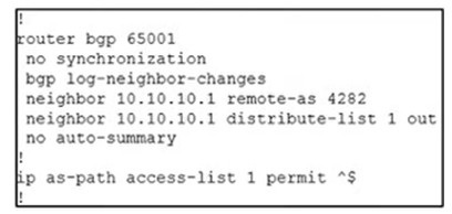
An engineer is reviewing the BGP configuration. Which routes must be advertised to 10.10.10.1
A. Local routes are permitted, and routes from other ASNs are denied.
B. All routes whether local or from other ASNs are denied.
C. Local routes are denied, and routes from other ASNs are permitted.
D. All routes whether local or from other ASNs are permitted
Explanation
The exhibit shows a BGP configuration with `neighbor 10.10.10.1 distribute-list 1 out` and `ip as-path access-list 1 permit ^$`. The AS-path access list entry `permit ^$` matches routes with an empty AS_PATH. An empty AS_PATH means the route originated locally within the local AS (AS 65001) and was not learned from any other AS. Therefore, only local routes are permitted to be advertised to neighbor `10.10.10.1`, while routes learned from other ASNs (which have non-empty AS_PATHs) are denied by the implicit deny at the end of the access list. This makes option A the correct answer.
Why the other options are incorrect:
B. All routes, whether local or from other ASNs, are denied
This is incorrect because the `permit ^$` statement explicitly permits local routes with empty AS_PATHs. Only routes from other ASNs are denied.
C. Local routes are denied, and routes from other ASNs are permitted
This is the opposite of what the configuration does. The `permit ^$` statement permits local routes (empty AS_PATH) and denies routes with non-empty AS_PATHs.
D. All routes, whether local or from other ASNs, are permitted
This is incorrect because the access list only permits routes with empty AS_PATHs. Routes from other ASNs have non-empty AS_PATHs and are denied.
Reference:
Cisco IOS XR Routing Configuration Guide – Implementing BGP: AS-Path Access Lists and Distribute Lists; RFC 4271 – A Border Gateway Protocol 4 (BGP-4); Cisco 350-501 SPCOR Official Cert Guide, BGP chapter.
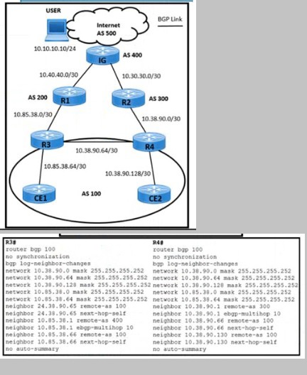
Refer to the exhibit. The USER mat is connecting an application on an Internet connection
in AS 100 is facing these issues:
The USER lost the connection to the application during a failure Between IG and R2. Router R2 configuration a lost due to a power outage.
The application the USER is connecting to a hosted behind CE2.
What action resolves the issues on R3 and R4 routers?
A. Set R4 as a route reflector for R3 and CE2
B. Apply high Local Preference on R3 toward R1
C. Set R3 as a route reflector for R4 and CE1
D. Apply low Local Preference on R4 toward R2.
Explanation
The scenario describes a failure between IG and R2, with R2's configuration lost due to a power outage, and the USER in AS 100 needs to reach an application hosted behind CE2. To resolve the issue on R3 and R4, the best action is to set R4 as a route reflector for R3 and CE2. This ensures that iBGP routes are properly reflected between R3, R4, and CE2, maintaining BGP reachability within AS 100 even when one path (via R2) is lost. Since R3 and R4 are iBGP peers within the same AS, and CE2 is also in AS 100, configuring R4 as a route reflector allows it to reflect routes between R3 and CE2, providing an alternate path and restoring connectivity for the USER's application. This makes option A the correct answer.
Why the other options are incorrect:
B. Apply high Local Preference on R3 toward R1
Local preference affects outbound path selection within AS 100. Setting a high local preference on R3 toward R1 would influence which exit point R3 prefers, but it does not address the iBGP reachability issue caused by the failure between IG and R2 or the loss of R2's configuration.
C. Set R3 as a route reflector for R4 and CE1
While route reflection is a valid solution, setting R3 as the route reflector for R4 and CE1 does not directly address the requirement to reach the application behind CE2. R4 as the route reflector for R3 and CE2 is more appropriate because CE2 hosts the application the USER needs to reach.
D. Apply low Local Preference on R4 toward R2
R2 is in AS 200, and local preference is used for outbound path selection within the local AS. Setting a low local preference on R4 toward R2 would make the path via R2 less preferred, but the issue is not about path preference; it is about restoring iBGP reachability after R2's failure. This action does not resolve the connectivity problem.
Reference:
RFC 4456 – BGP Route Reflection: An Alternative to a Full Mesh Internal BGP (IBGP); RFC 4271 – A Border Gateway Protocol 4 (BGP-4); Cisco 350-501 SPCOR Official Cert Guide, BGP chapter.
Drag and drop the functionalities from the left onto the target fields on the right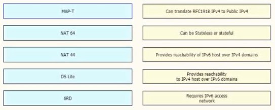
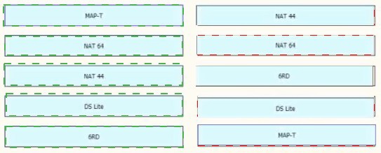
Explanation:
The exhibit requires matching each IPv6 transition technology with its correct functionality. NAT44 translates RFC1918 private IPv4 addresses to public IPv4 addresses. NAT64 can operate in either stateless or stateful mode to translate between IPv6 and IPv4. 6RD (IPv6 Rapid Deployment) provides reachability to IPv4 hosts over IPv6 domains by encapsulating IPv4 traffic within IPv6. DS Lite (Dual-Stack Lite) requires an IPv6 access network to tunnel IPv4 traffic over the IPv6 infrastructure. MAP-T provides reachability of IPv6 hosts over IPv4 domains using stateless IPv4-to-IPv6 mapping and translation. This makes the correct matches as follows:
NAT44 → Can translate RFC1918 IPv4 to Public IPv4
NAT64 → Can be Stateless or stateful
6RD → Provides reachability to IPv4 host over IPv6 domains
DS Lite → Requires IPv6 access network
MAP-T → Provides reachability of IPv6 host over IPv4 domains
Why the other pairings are incorrect:
Matching MAP-Twith the "Can translate RFC1918 IPv4 to Public IPv4" description is incorrect because that describes NAT44, not MAP-T. MAP-T is a stateless IPv4-to-IPv6 mapping and translation mechanism that allows IPv6 hosts to communicate with IPv4 resources.
Matching NAT64 with the "Provides reachability of IPv6 host over IPv4 domains" description is incorrect because that is the role of MAP-T. NAT64 allows IPv6-only hosts to reach IPv4 servers by translating IPv6 packets to IPv4, which is the opposite direction.
Matching DS Lite with the "Provides reachability to IPv4 host over IPv6 domains" description is incorrect because that describes 6RD. DS Lite requires an IPv6 access network and uses IPv4-in-IPv6 tunneling with carrier-grade NAT.
Matching 6RD with the "Requires IPv6 access network" description is incorrect because 6RD provides IPv6 connectivity over an existing IPv4 access network, not the other way around. DS Lite is the technology that requires an IPv6 access network.
Reference:
RFC 2663 – IP Network Address Translator (NAT) Terminology and Considerations; RFC 6146 – Stateful NAT64; RFC 5569 – IPv6 Rapid Deployment on IPv4 Infrastructures (6rd); RFC 6333 – Dual-Stack Lite Broadband Deployments Following IPv4 Exhaustion; RFC 7599 – Mapping of Address and Port using Translation (MAP-T); Cisco 350-501 SPCOR Official Cert Guide, Architecture and Services section.
| Page 19 out of 55 Pages |