• 4.9/5.0
  • 547 Questions
  • Updated on: 12-Oct-2026
  • Implementing and Operating Cisco Service Provider Network Core Technologies (350-501 SPCOR)
  • 25475 Prepared

Free Cisco 350-501 Practice Questions 2026 | Implementing and Operating Cisco Service Provider Network Core Technologies (350-501 SPCOR)


Which feature describes the adjacency SID?

A. It applies only to point-to-point links.

B. It applies only to multipoint links

C. It is locally unique

D. It is globally unique

C.   It is locally unique

Explanation

An Adjacency SID (Adj-SID) in Segment Routing is a local identifier that is locally unique within the router that advertises it. It identifies a specific adjacency (link or neighbor) on that router, and its value only needs to be unique within that router's SR database. Unlike a Prefix-SID, which must be globally unique within the SR domain, an Adjacency SID is significant only on the local router and is not required to be unique across the entire domain. This makes option C the correct answer.

Why the other options are incorrect:

A. It applies only to point-to-point links
Adjacency SIDs can be used on point-to-point links, but they can also be used on other interface types, including broadcast and point-to-multipoint links, depending on the implementation and configuration. The statement is too restrictive.

B. It applies only to multipoint links
Adjacency SIDs are not limited to multipoint links. They apply to any adjacency that the router advertises, including point-to-point links.

D. It is globally unique
Globally unique identifiers are Prefix-SIDs, not Adjacency SIDs. Adjacency SIDs are locally significant and only need to be unique within the router that originates them.

Reference:
RFC 8402 – Segment Routing Architecture; Cisco IOS XR Segment Routing Configuration Guide – Configuring Adjacency SIDs; Cisco 350-501 SPCOR Official Cert Guide, Segment Routing chapter.

Which type of attack is a Protocol attack?

A. HTTP flood

B. HTTP flood

C. SYN flood

D. Slowlorls

C.   SYN flood

Explanation

An Adjacency SID (Adj-SID) in Segment Routing is a local identifier that is locally unique within the router that advertises it. It identifies a specific adjacency (link or neighbor) on that router, and its value only needs to be unique within that router's SR database. Unlike a Prefix-SID, which must be globally unique within the SR domain, an Adjacency SID is significant only on the local router and is not required to be unique across the entire domain. This makes option C the correct answer.

Why the other options are incorrect:

A. It applies only to point-to-point links
Adjacency SIDs can be used on point-to-point links, but they can also be used on other interface types, including broadcast and point-to-multipoint links, depending on the implementation and configuration. The statement is too restrictive.

B. It applies only to multipoint links
Adjacency SIDs are not limited to multipoint links. They apply to any adjacency that the router advertises, including point-to-point links.

D. It is globally unique
Globally unique identifiers are Prefix-SIDs, not Adjacency SIDs. Adjacency SIDs are locally significant and only need to be unique within the router that originates them.

Reference:
RFC 8402 – Segment Routing Architecture; Cisco IOS XR Segment Routing Configuration Guide – Configuring Adjacency SIDs; Cisco 350-501 SPCOR Official Cert Guide, Segment Routing chapter.

A network administrator is planning a new network with a segment-routing architecture using a distributed control plane. How is routing information distributed on such a network?

A. Each segment is signalled by an SR controller, but each segment makes Its own steering decisions based on SR policy.

B. Each segment is signalled by MPLS, and each segment makes steering decisions based on the routing policy pushed by BGP.

C. Each segment is signalled by an SR controller that makes the steering decisions for each node.

D. Each segment is signalled by a compatible routing protocol and each segment makes its own steering decisions based on SR policy

D.   Each segment is signalled by a compatible routing protocol and each segment makes its own steering decisions based on SR policy

Explanation

In a Segment Routing architecture with a distributed control plane, routing information is distributed by a compatible routing protocol such as OSPF or IS-IS (extended with Segment Routing extensions). Each router in the SR domain receives the Prefix-SIDs and Adjacency SIDs via the IGP, and each node independently makes its own steering decisions based on the SR policy configured or computed locally. There is no central SR controller in a distributed control plane design; the control plane is distributed across the routers, and each node computes its own forwarding decisions using the SR SID list. This makes option D the correct answer.

Why the other options are incorrect:

A. Each segment is signalled by an SR controller, but each segment makes its own steering decisions based on SR policy
This describes a centralized control plane design, where an SR controller (PCE) signals segments. The question specifies a distributed control plane, so an SR controller is not used for signaling.

B. Each segment is signalled by MPLS, and each segment makes steering decisions based on the routing policy pushed by BGP
Segment Routing does not use MPLS LDP or BGP to signal segments in a distributed control plane. Segments are signaled by the IGP (OSPF/IS-IS) with SR extensions, not by MPLS or BGP.

C. Each segment is signalled by an SR controller that makes the steering decisions for each node
This describes a centralized SR controller architecture, which contradicts the requirement for a distributed control plane where each node makes its own decisions.

Reference:
RFC 8402 – Segment Routing Architecture; RFC 8665 – OSPF Extensions for Segment Routing; RFC 5305 – IS-IS Extensions for Traffic Engineering; Cisco 350-501 SPCOR Official Cert Guide, Segment Routing chapter.

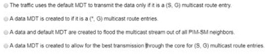
What occurs when a high bandwidth multicast stream is sent over an MVPN using Cisco hardware?
A. Option A

B. Option B

C. Option C

D. Option D

D.   Option D

Explanation

In an MVPN (Multicast Virtual Private Network) using Cisco hardware, when a high-bandwidth multicast stream is sent, a data MDT (Multicast Distribution Tree) is created to carry the traffic for (S, G) multicast route entries. The default MDT is used for low-bandwidth or control traffic and for initial stream discovery, but once the traffic rate exceeds the configured threshold, the PE router signals the creation of a data MDT to optimize the transmission through the core. This allows the high-bandwidth stream to be carried on a dedicated tree that is better suited for the traffic, rather than flooding it across the default MDT to all PE routers. This makes option D the correct answer.

Why the other options are incorrect:

A. The traffic uses the default MDT to transmit the data only if it is a (S, G) multicast route entry
The default MDT is used for initial traffic and low-bandwidth streams, but high-bandwidth streams trigger the creation of a data MDT. The statement is incomplete and does not describe the data MDT creation.

B. A data MDT is created if it is a (*, G) multicast route entry
A data MDT is created for (S, G) entries, not (*, G) entries. The (*, G) entries are shared-tree entries and are typically carried on the default MDT.

C. A data and default MDT are created to flood the multicast stream out of all PIM-SM neighbors
This is incorrect because the purpose of the data MDT is to avoid flooding the stream to all PE routers. Only the default MDT floods to all peers; the data MDT is selective.

Reference:
RFC 6037 – Cisco Systems' Solution for Multicast in BGP/MPLS IP VPNs; Cisco IOS XR Multicast Configuration Guide – Configuring MVPN Data MDT; Cisco 350-501 SPCOR Official Cert Guide, Multicast chapter.

What is a constraint of Cisco MPLS TE tunnel configurations?

A. Tunnels cannot span multiple OSPF areas.

B. With ISIS as an IGP. only older-style metrics are used.

C. Tunnels cannot be configured over IP unnumbered links.

D. QoS-aware tunneling is not supported.

A.   Tunnels cannot span multiple OSPF areas.

Explanation

A constraint of Cisco MPLS TE tunnel configurations is that tunnels cannot span multiple OSPF areas. MPLS TE uses the IGP's TE extensions to flood link-state information (including bandwidth and TE metrics) within a single area. The TE topology database (TED) is built per area, and CSPF path computation is performed within that area. Because TE information is not flooded across OSPF area boundaries, a TE tunnel's explicit or dynamic path cannot be computed across multiple areas without additional mechanisms such as inter-area TE extensions (which are not standard in Cisco MPLS TE). Therefore, MPLS TE tunnels are confined to a single OSPF area. This makes option A the correct answer.

Why the other options are incorrect:

B. With ISIS as an IGP, only older-style metrics are used
IS-IS TE extensions support both narrow and wide metrics. The wide metric (32-bit) is used for TE and is not limited to older-style narrow metrics. This statement is false.

C. Tunnels cannot be configured over IP unnumbered links
MPLS TE tunnels can be configured over IP unnumbered links. TE extensions support unnumbered links by using the router ID and interface index to identify the link. This statement is false.

D. QoS-aware tunneling is not supported
MPLS TE supports QoS-aware tunneling through the use of TE classes, affinity, and bandwidth reservations. DS-TE (DiffServ-aware TE) extends this further. This statement is false.

Reference:
RFC 3630 – Traffic Engineering (TE) Extensions to OSPF Version 2; RFC 5305 – IS-IS Extensions for Traffic Engineering; Cisco IOS XR MPLS Configuration Guide – Implementing MPLS Traffic Engineering; Cisco 350-501 SPCOR Official Cert Guide, MPLS Traffic Engineering chapter.

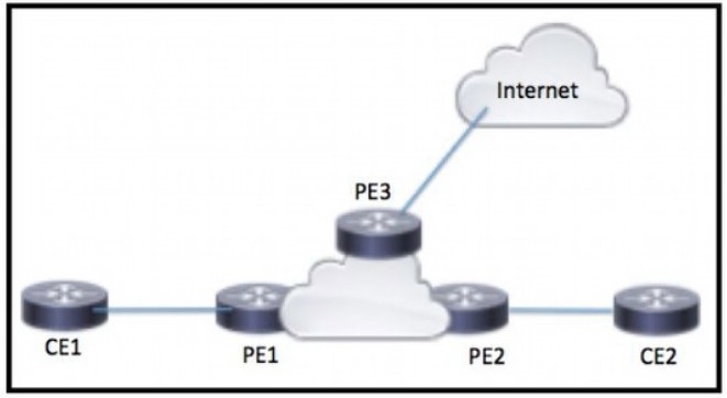
Refer to the exhibit

CE1 and CE2 require connectivity to the internet through the ISP connected to PE3 What should an engineer configure to complete this task?

A. PE2 must be configured to serve as a route reflector for PE3 routes learned from the internet. PE2 then shares the routes with CE1 and CE2.

B. CE1 and CE2 must be configured with a route distinguisher in the PE1 VRF that dynamically imports the route from the internet.

C. CE1 and CE2 must be configured to use a static default route with a next-hop of PE3 to reach internet routes.

D. PE1 must be configured with an import route target in the CE1 VRF that matches the export route target for the internet VRF on PE3.

D.   PE1 must be configured with an import route target in the CE1 VRF that matches the export route target for the internet VRF on PE3.

Explanation

The scenario shows CE1 and CE2 connected to an MPLS VPN provider and needing Internet access through PE3, which is connected to the Internet. To provide Internet access to the VPN customers, the Internet routes must be imported into the customer VRF. This is accomplished by configuring an import route target in the CE1 VRF on PE1 that matches the export route target of the Internet VRF on PE3. This route target matching causes PE3 to export the Internet routes into the Internet VRF, and PE1 to import those routes into the customer VRF, making them available to CE1 (and similarly for CE2). This is the standard shared services/Internet access design in MPLS L3VPN. This makes option D the correct answer.

Why the other options are incorrect:

A. PE2 must be configured to serve as a route reflector for PE3 routes learned from the Internet. PE2 then shares the routes with CE1 and CE2
PE2 is a provider (P) router, not a route reflector for Internet routes. Internet access in an MPLS L3VPN is provided through route target import/export between the customer VRF and the Internet VRF, not through route reflection.

B. CE1 and CE2 must be configured with a route distinguisher in the PE1 VRF that dynamically imports the route from the Internet
Route distinguishers (RDs) are used to make VPNv4 prefixes unique; they do not control import of routes from the Internet. Route targets, not RDs, control import/export between VRFs.

C. CE1 and CE2 must be configured to use a static default route with a next-hop of PE3 to reach Internet routes
The CE routers are not directly connected to PE3 and cannot use PE3 as a next-hop. Internet access is provided through the MPLS VPN infrastructure, not through a direct static route to PE3 on the CE side.

Reference:
RFC 4364 – BGP/MPLS IP Virtual Private Networks (VPNs); Cisco IOS XR MPLS Configuration Guide – Implementing MPLS L3VPN: Internet Access and Route Targets; Cisco 350-501 SPCOR Official Cert Guide, MPLS L3VPN chapter.

After a series of unexpected device failures on the network. a Cisco engineer is deploying NSF on the network devices so that packets continue to be forwarded during switchovers The network devices reside in the same holding, but they are physically separated into two different data centers Which task must the engineer perform as part of the deployment?

A. implement OSPF to maintain the link-state database during failover.

B. implement VRFs ana specify the forwarding instances that must remain active during failover.

C. implement an L2VPN with the failover peer to share state Information between the active and standby devices.

D. implement Cisco Express Forwarding to provide forwarding during failover

C.   implement an L2VPN with the failover peer to share state Information between the active and standby devices.

Explanation

Non-Stop Forwarding (NSF) with Stateful Switchover (SSO) requires that the control-plane state and forwarding information be synchronized between the active and standby Route Processors (RPs) or between the active and standby devices. When the network devices reside in two different data centers but in the same building, the engineer must implement an L2VPN between the failover peers to share state information between the active and standby devices. This allows the standby device to receive the synchronized state (such as routing tables, CEF entries, and protocol state) so that forwarding can continue during a switchover. This makes option C the correct answer.

Why the other options are incorrect:

A. Implement OSPF to maintain the link-state database during failover
OSPF is a routing protocol, not a mechanism to synchronize state between active and standby devices. NSF for OSPF helps maintain the LSDB during a restart, but it does not provide the inter-device state synchronization needed when the devices are physically separate.

B. Implement VRFs and specify the forwarding instances that must remain active during failover
VRFs provide logical separation of routing and forwarding tables, but they do not synchronize state between active and standby devices. This does not address the requirement for state sharing during failover.

D. Implement Cisco Express Forwarding to provide forwarding during failover
CEF is the forwarding mechanism that NSF preserves, but it does not by itself provide state synchronization between active and standby devices across two data centers. CEF alone does not enable NSF/SSO across separate devices.

Reference:
Cisco IOS XR High Availability Configuration Guide – Non-Stop Forwarding and Stateful Switchover; Cisco 350-501 SPCOR Official Cert Guide, Network Assurance and High Availability sections.

Which protocol is used for communication between the PCE and PCC?

A. ICMP

B. PCEP

C. CEF

D. POP

B.   PCEP

Explanation

The Path Computation Element (PCE) communicates with the Path Computation Client (PCC) using the Path Computation Element Communication Protocol (PCEP). PCEP is defined in RFC 5440 and is used by a PCC to send path computation requests to a PCE and receive replies with the computed paths. This makes option B the correct answer.

Why the other options are incorrect:

A. ICMP
ICMP is used for network diagnostics and error reporting (such as ping and traceroute), not for PCE-PCC communication.

C. CEF
Cisco Express Forwarding is a forwarding mechanism used on Cisco routers for packet switching, not a communication protocol between PCE and PCC.

D. POP
POP (Post Office Protocol) is an email retrieval protocol and has no role in MPLS TE path computation.

Reference:
RFC 5440 – Path Computation Element (PCE) Communication Protocol (PCEP); RFC 4655 – A Path Computation Element (PCE)-Based Architecture; Cisco IOS XR MPLS Configuration Guide – Configuring MPLS TE with PCE; Cisco 350-501 SPCOR Official Cert Guide, MPLS Traffic Engineering chapter.

How is a telemetry session established for data analytics?

A. A router initiates a session using the dial-out to a destination.

B. A destination initiate a session to a router.

C. The destination initiate a session using the dial-out more to the router.

D. A router requests the data using Teinet.

A.   A router initiates a session using the dial-out to a destination.

Explanation

In model-driven telemetry, a session for data analytics can be established in two ways: dial-in and dial-out. In the dial-out model, the router (the telemetry source) initiates the session by connecting to a destination collector. This is the correct description for a router-initiated telemetry session. The router pushes the telemetry data to the collector at the configured interval. This makes option A the correct answer.

Why the other options are incorrect:

B. A destination initiates a session to a router
This describes the dial-in model, where the collector (destination) initiates the session to the router. The question asks how a telemetry session is established for data analytics, and the dial-out model (router initiates) is one valid and commonly tested method. However, if the intended answer is specifically about the router initiating, then option B describes the opposite direction and is incorrect for dial-out.

C. The destination initiates a session using the dial-out mode to the router
This is contradictory: dial-out is router-initiated, not destination-initiated. The wording is also incorrect ("dial-out mode").

D. A router requests the data using Telnet
Telemetry does not use Telnet. It uses gRPC, NETCONF, or RESTCONF over HTTP/2 for dial-in, or gRPC for dial-out. Telnet is a legacy CLI protocol, not a telemetry transport.

Reference:
Cisco IOS XR Telemetry Configuration Guide – Model-Driven Telemetry: Dial-In and Dial-Out; RFC 7950 – The YANG 1.1 Data Modeling Language; Cisco 350-501 SPCOR Official Cert Guide, Automation and Assurance section.

Which OoS model allows hosts to report their QoS needs to the network?

A. DiffServ

B. CB-WFQ

C. IntServ

D. MQC

C.   IntServ

Explanation

The Integrated Services (IntServ) QoS model allows hosts to signal their QoS requirements to the network before sending data, using a signaling protocol such as RSVP. The host requests a specific level of service (for example, guaranteed bandwidth or bounded delay), and the network reserves resources along the path to meet that request. This explicit signaling from hosts to the network is the defining characteristic of IntServ. This makes option C the correct answer.

Why the other options are incorrect:

A. DiffServ
Differentiated Services classifies and marks traffic into behavior aggregates and applies per-hop behaviors based on those markings. It does not provide a mechanism for individual hosts to signal their QoS needs to the network.

B. CB-WFQ
Class-Based Weighted Fair Queuing is a queuing mechanism used within a router to provide differentiated scheduling for different traffic classes. It is not a QoS model for host-to-network signaling.

D. MQC
The Modular QoS CLI is a Cisco configuration framework for defining and applying QoS policies (class maps, policy maps, service policies). It is a configuration tool, not a QoS model for host signaling.

Reference:
RFC 1633 – Integrated Services in the Internet Architecture: an Overview; RFC 2475 – An Architecture for Differentiated Services; Cisco 350-501 SPCOR Official Cert Guide, QoS section.

Page 20 out of 55 Pages