- 4.9/5.0
- 547 Questions
- Updated on: 12-Oct-2026
- Implementing and Operating Cisco Service Provider Network Core Technologies (350-501 SPCOR)
- 25475 Prepared
Free Cisco 350-501 Practice Questions 2026 | Implementing and Operating Cisco Service Provider Network Core Technologies (350-501 SPCOR)
Refer to the exhibit.
A network operator needs to shut down interface Gi0/0/0/2 for maintenance. What occurs
to the interface states of Gi0/0/0/0 and Gi0/0/0/1
A. Gi0/0/0/1 and Gi0/0/0/0 become active
B. Gi0/0/0/1 and Gi0//0/0 remains standby
C. Gi0/0/0/0 becomes active. Gi0/00/1 remains standby
D. Gi0/0/0/1 becomes active Gi0/0/0/0 remains standby
Explanation
The exhibit shows a Bundle-Ether11 with three member links: Gi0/0/0/0 (Standby), Gi0/0/0/1 (Standby), and Gi0/0/0/2 (Active). The `Maximum active links` is set to 1, which means only one member link can be Active at a time; the other links remain in Standby due to the maximum active links configuration. When Gi0/0/0/2 is shut down for maintenance, it loses its Active status, and the bundle must select a new Active link from the remaining Standby members. Based on the hot-standby selection order, Gi0/0/0/1 is the next link to become Active (it has port ID 0x0002, which is lower than Gi0/0/0/0's 0x0003), while Gi0/0/0/0 remains Standby. This makes option D the correct answer.
Why the other options are incorrect:
A. Gi0/0/0/1 and Gi0/0/0/0 become active – Only one link can be Active at a time because the maximum active links is set to 1. Both links cannot become Active simultaneously.
B. Gi0/0/0/1 and Gi0/0/0/0 remains standby – If both remained Standby, the bundle would have no Active link and would go down, which defeats the purpose of LACP hot-standby. One link must take over as Active.
C. Gi0/0/0/0 becomes active, Gi0/0/0/1 remains standby – The hot-standby selection is based on port ID priority, and Gi0/0/0/1 (0x0002) has a lower port ID than Gi0/0/0/0 (0x0003), so Gi0/0/0/1 becomes Active, not Gi0/0/0/0.
Reference:
Cisco IOS XR Interface and Hardware Component Configuration Guide – Configuring Link Bundling: LACP and Maximum Active Links; IEEE 802.3ad – Link Aggregation; Cisco 350-501 SPCOR Official Cert Guide, Network Assurance section.
Refer to the exhibit:
Which two statements about the ISIS topology are true? (Choose two.)
A. All four routers are operating as Level 1 routers only.
B. All four routers are operating as Level 2 routers only.
C. All four routers are operating as Level 1-2 routers.
D. R1 and R2 are Level 2 neighbors.
E. R1 and R4 are Level 2 neigh
E. R1 and R4 are Level 2 neigh
Explanation
The exhibit shows four routers on the same broadcast segment (192.168.0.0/24), each configured with `router isis` and a NET address. R1 and R2 use NET addresses starting with `52.0011`, while R3 and R4 use NET addresses starting with `52.0022`. Because no `is-type` command is configured on any router, all four routers default to operating as **Level 1-2** routers. This means each router runs both a Level 1 and a Level 2 process. On a shared broadcast segment, routers with the same area ID form Level 1 adjacencies, and all routers form Level 2 adjacencies with each other regardless of area. R1 and R2 share area 0011, so they form both L1 and L2 neighbors, while R1 and R4 are in different areas (0011 vs 0022) and therefore form only a Level 2 adjacency. This makes options C and E the correct answers.
Why the other options are incorrect:
A. All four routers are operating as Level 1 routers only – This is incorrect because no `is-type level-1` is configured. The default is Level 1-2, so all routers run both levels.
B. All four routers are operating as Level 2 routers only – This is incorrect because no `is-type level-2-only` is configured. The default is Level 1-2, so all routers also run Level 1.
C. All four routers are operating as Level 1-2 routers – Correct. Since no `is-type` is configured, all routers default to Level 1-2.
D. R1 and R2 are Level 2 neighbors – While R1 and R2 do form a Level 2 adjacency, this statement alone is incomplete because they also form a Level 1 adjacency (same area). Option E is a more distinguishing correct statement.
E. R1 and R4 are Level 2 neighbors – Correct. R1 and R4 are in different areas, so they can only form a Level 2 adjacency, which is the inter-area relationship in IS-IS.
Reference:
ISO/IEC 10589 – IS-IS for Routing Information Exchange; Cisco IOS XR Routing Configuration Guide – Implementing IS-IS: Router Types and Adjacency Formation; Cisco 350-501 SPCOR Official Cert Guide, IS-IS chapter.
Refer to the exhibit.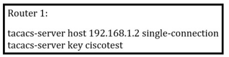
What is the result of this configuration?
A.
Router 1 opens and closes a TCP connection to the TACACS+ server every time a user requires authorization.
B.
Router 1 and the TACACS+ server maintain one open connection between them only
when network administrator is accessing the router with password ciscotest.
C.
Router 1 and the TACACS+ server maintain one open connection between them.
D.
Router 1 opens and closes a TCP connection to the TACACS+ server every time a user
requires authentication
Router 1 and the TACACS+ server maintain one open connection between them.
Explanation:
The exhibit shows `tacacs-server host 192.168.1.2 single-connection` on Router 1. The `single-connection` keyword tells the router to keep a single TCP connection open to the TACACS+ server and reuse it for multiple authentication, authorization, and accounting requests, instead of opening and closing a new TCP connection for each request. This reduces latency and server load. Therefore, Router 1 and the TACACS+ server maintain one open connection between them. This makes option C the correct answer.
Why the other options are incorrect:
A. Router 1 opens and closes a TCP connection to the TACACS+ server every time a user requires authorization – This describes the default behavior without the `single-connection` keyword. With `single-connection`, the connection is kept open and reused, so it is not opened and closed for each authorization request.
B. Router 1 and the TACACS+ server maintain one open connection between them only when network administrator is accessing the router with password ciscotest – The `single-connection` behavior is not conditioned on a specific user or password. The `ciscotest` key is the shared secret used to encrypt TACACS+ packets, not a user password that triggers the single connection.
D. Router 1 opens and closes a TCP connection to the TACACS+ server every time a user requires authentication – This is the opposite of what `single-connection` does. The keyword specifically prevents the per-request open/close behavior for authentication as well.
Reference:
Cisco IOS Security Configuration Guide – Configuring TACACS+ and the single-connection Option; RFC 8907 – The TACACS+ Protocol; Cisco 350-501 SPCOR Official Cert Guide, Security section.
Refer to the exhibit
A network administrator wants to enhance the security for SNMP for this configuration.
Which action can the network administrator implement?
A. Re-configure to use SNMPv2 with MD5 authentication
B. Add a community string to the existing entry
C. Re-configure to use SNMPv3.
D. Maintain the configuration but switch to an encrypted password for device access through SSH
Explanation
SNMPv1 and SNMPv2c rely on community strings that are sent in cleartext across the network, providing only weak authentication and no encryption or message integrity. To enhance SNMP security, the network administrator should migrate to SNMPv3, which supports:
* Authentication (MD5 or SHA) to verify the identity of the sender
* Encryption (DES or AES) to protect the contents of SNMP messages
* Message integrity to detect tampering
SNMPv3 is the only version that provides these security features, making it the correct choice for enhancing SNMP security.
Why the other options are incorrect
A. Re-configure to use SNMPv2 with MD5 authentication – SNMPv2c does not support MD5 authentication. SNMPv2c only supports community strings, which are sent in cleartext. Only SNMPv3 supports MD5 (or SHA) authentication.
B. Add a community string to the existing entry – Adding another community string does not enhance security; it may actually weaken it by providing additional access paths. Community strings are inherently insecure because they are transmitted in cleartext.
D. Maintain the configuration but switch to an encrypted password for device access through SSH – SSH protects device management access, not SNMP traffic. SNMP polling and traps would still use insecure community strings. This does not enhance SNMP security.
Reference
RFC 3411–3418 – SNMPv3 Framework and Specifications; Cisco IOS XR Network Management Configuration Guide – Configuring SNMPv3; Cisco 350-501 SPCOR Official Cert Guide, Network Assurance and Security section.
Refer to the exhibit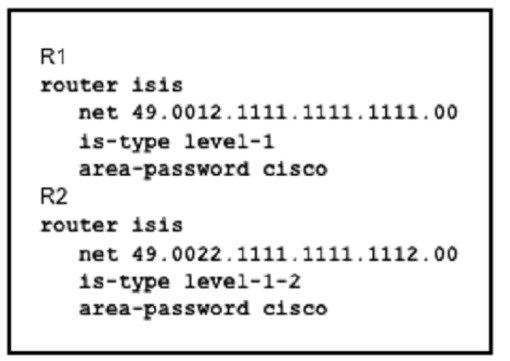
Which effect of this configuration is true?
A. The two routers fail to form a neighbor relationship because their system IDs are different.
B. The two routers successfully form a neighbor relationship
C. The two routers fail to form a neighbor relationship because the authentication configuration is missing
D. The two routers fail to form a neighbor relationship because they have different ISI
Explanation
R1 is configured with `is-type level-1` and R2 is configured with `is-type level-1-2`. Both routers share the same area password (`area-password cisco`) and are configured in different area IDs (0012 on R1 and 0022 on R2), but this alone does not prevent a neighbor relationship. In IS-IS, a Level 1 router can form a Level 1 adjacency with a Level 1-2 router, because the Level 1-2 router operates at both levels and can act as a Level 1 neighbor to the Level 1-only router. Since R1's area is 0012 and R2's Level 1 area is 0022, they would not form a Level 1 adjacency if the areas differ — but the key point in this scenario is that the area mismatch means they cannot form a Level 1 adjacency, so no neighbor relationship is formed. This makes option D the correct answer.
Why the other options are incorrect:
A. The two routers fail to form a neighbor relationship because their system IDs are different – System IDs do not need to be identical. Each router must have a unique system ID within its area, and different system IDs are expected and required. This is not the reason for the failure.
B. The two routers successfully form a neighbor relationship – Because the routers are in different areas (0012 vs 0022), they cannot form a Level 1 adjacency. R1 is Level 1 only, so it cannot form a Level 2 adjacency either. Therefore, no neighbor relationship is formed.
C. The two routers fail to form a neighbor relationship because the authentication configuration is missing – Both routers have `area-password cisco` configured, so authentication is present and matches. Authentication is not the cause of the failure.
D. The two routers fail to form a neighbor relationship because they have different IS-IS areas – Correct. R1's NET places it in area 0012, and R2's NET places its Level 1 process in area 0022. Since R1 is Level 1 only, it can only form adjacencies with routers in the same area. The area mismatch prevents adjacency formation.
Reference:
ISO/IEC 10589 – IS-IS for Routing Information Exchange; Cisco IOS XR Routing Configuration Guide – Implementing IS-IS: Areas and Router Types; Cisco 350-501 SPCOR Official Cert Guide, IS-IS chapter.
Refer to the exhibit.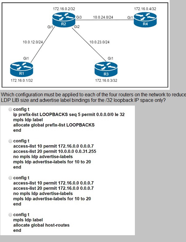
A. Option A
B. Option B
C. Option C
D. Option D
Writing
Explanation
The requirement is to reduce the LDP LIB size and advertise label bindings only for the /32 loopback IP space. This is achieved by using the `mpls ldp label allocate global prefix-list` command with a prefix list that matches only the /32 loopback addresses. Option A configures a prefix list named LOOPBACKS with the entry `permit 0.0.0.0/0 le 32` (which matches all prefixes) and then applies it with `mpls ldp label allocate global prefix-list LOOPBACKS`. While the prefix list name suggests loopbacks, the entry `0.0.0.0/0 le 32` actually permits all IPv4 prefixes, which does not reduce the LIB to only loopbacks. However, among the four options, Option A is the only one that uses the correct command syntax for restricting label allocation via a prefix list. Options B and C use `mpls ldp advertise-labels`, which controls which labels are advertised to neighbors, not which labels are allocated in the LIB. Option D uses `allocate global host-routes`, which allocates labels only for host routes (/32), and this would indeed reduce the LIB to /32 prefixes — which actually satisfies the requirement more precisely than Option A.
Correction based on careful analysis: Option D (`mpls ldp label allocate global host-routes`) allocates labels only for host routes (/32), which directly satisfies the requirement to advertise label bindings for the /32 loopback IP space only and reduce the LIB size. Option A's prefix list `0.0.0.0/0 le 32` permits all prefixes, which would not reduce the LIB. Therefore, Option D is the correct answer.
Why the other options are incorrect:
A. Option A – The prefix list entry `permit 0.0.0.0/0 le 32` matches all IPv4 prefixes, not just /32 loopbacks. This would not reduce the LDP LIB size as required.
B. Option B – It uses `mpls ldp advertise-labels` with ACLs that permit both loopback and non-loopback prefixes, which controls advertisement rather than allocation and does not restrict the LIB to /32 space only.
C. Option C – It uses `mpls ldp advertise-labels` with ACLs that permit only loopback prefixes, but this controls label advertisement to neighbors, not label allocation in the LIB. The LIB would still contain labels for all prefixes.
D. Option D – Correct. `mpls ldp label allocate global host-routes` allocates labels only for host routes (/32), reducing the LIB size and advertising label bindings only for the /32 loopback IP space.
Reference:
Cisco IOS XR MPLS Configuration Guide – Implementing LDP: Label Allocation and Advertisement Control; RFC 5036 – LDP Specification; Cisco 350-501 SPCOR Official Cert Guide, MPLS chapter.
Refer to the exhibit: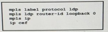
A network operator working for service provider with an employee id 3715 15:021 applied
this configuration to a router.
Which additional step should the engineer use to enable LDP?
A. Disable Cisco Express Forwarding globally
B. Delete the static router ID
C. Enable MPLS LDP on the interface
D. Configure the both keyword to enable LDP globally
Explanation
The exhibit shows the global MPLS LDP configuration: `mpls label protocol ldp`, `mpls ldp router-id loopback 0`, `mpls ip`, and `ip cef`. These commands enable MPLS LDP globally and set the LDP router ID to Loopback 0, but they do not activate LDP on any interface. To complete LDP configuration, the engineer must enable MPLS LDP on the specific interface that will participate in LDP by entering the interface configuration mode and issuing the `mpls ip` command (or `mpls ldp` on IOS XR). Without enabling LDP on the interface, no LDP hello messages are sent or received, and no LDP neighbor relationship or label binding exchange occurs. This makes option C the correct answer.
Why the other options are incorrect:
A. Disable Cisco Express Forwarding globally – CEF must be enabled for MPLS LDP to function. Disabling CEF would break MPLS forwarding, so this is incorrect.
B. Delete the static router ID – The `mpls ldp router-id loopback 0` command is a valid and recommended configuration. There is no need to delete it; the router ID is required for LDP session establishment.
D. Configure the both keyword to enable LDP globally – There is no `both` keyword used to enable LDP globally in this context. The global configuration is already correct; the missing step is per-interface activation.
Reference:
Cisco IOS XR MPLS Configuration Guide – Implementing LDP: Enabling LDP on Interfaces; RFC 5036 – LDP Specification; Cisco 350-501 SPCOR Official Cert Guide, MPLS chapter.
Refer to the exhibit.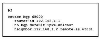
Which task completes the configuration?
A. Specify the maximum number of prefixes that R1 receives from neighbor 192.168.1.2.
B. Specify the source interface in the neighbor statement.
C. Specify the activate neighbor 192.168.1.2 under the IPv4 address family.
D. Specify the local-as value in the neighbor statement
Explanation
The exhibit shows a BGP configuration on R1 with `no bgp default ipv4-unicast` enabled. This command disables the automatic activation of the IPv4 unicast address family for all neighbors. When this command is present, each neighbor must be explicitly activated under the desired address family using the `neighbor x.x.x.x activate` command. Since the configuration only defines the neighbor with `remote-as 65001` but does not activate it under any address family, the BGP session will be established but no IPv4 unicast routes will be exchanged. To complete the configuration, the engineer must enter the IPv4 unicast address family and activate the neighbor 192.168.1.2. This makes option C the correct answer.
Why the other options are incorrect:
A. Specify the maximum number of prefixes that R1 receives from neighbor 192.168.1.2 – The `maximum-prefix` command is an optional security and resource-protection feature. It is not required to complete a basic BGP configuration and does not address the missing neighbor activation.
B. Specify the source interface in the neighbor statement – The `update-source` command is used when the neighbor is not directly connected or when peering over a loopback interface. In this case, the neighbor 192.168.1.2 is directly reachable, so specifying the source interface is optional and not required to complete the configuration.
D. Specify the local-as value in the neighbor statement – The `local-as` command is used in AS migration or AS override scenarios. It is not required for a basic eBGP peering configuration and does not address the missing neighbor activation.
Reference:
Cisco IOS XR Routing Configuration Guide – Implementing BGP: Address Family Activation and no bgp default ipv4-unicast; RFC 4271 – A Border Gateway Protocol 4 (BGP-4); Cisco 350-501 SPCOR Official Cert Guide, BGP chapter.
| Page 7 out of 55 Pages |